


9-4 Dell Precision 210 Desktop Systems User’s Guide
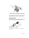
When attaching the interface cable to a drive, be sure to match the colored strip on
the cable to pin 1 of the drive’s interface connector. For the location of pin 1 on the
drive’s interface connector, see the documentation that came with the drive.
When disconnecting an interface cable from the system board, be sure to press in on
the locking tabs on the cable connector (if any) before disconnecting the cable. When
attaching an interface cable to the system board, be sure that the locking tabs snap
into place, ensuring that the cable is firmly attached to the connector on the system
board.
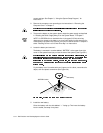
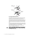
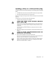
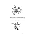
Most interface connectors are keyed for correct insertion; that is, a notch or a missing
pin on one connector matches a tab or a filled-in hole on the other connector (see Fig-
ure 9-4). Keying ensures that the pin-1 wire in the cable (indicated by the colored strip
along one edge of the cable) goes to the pin-1 end of the connector.
The pin-1 end of a connector on a board or a card is usually indicated by a silk-
screened “1” printed directly on the board or card.
header connector
on drive
interface
cables
card-edge connector
on drive
colored
strip
notch
colored
strip