


9-10 Dell Precision 210 Desktop Systems User’s Guide
,QVWDOOLQJDQ(,'(+DUG'LVN'ULYH
This section includes information on installing, partitioning, and formatting EIDE hard-
disk drives. Up to two 1-inch hard-disk drives or one 1-inch and one 1.6-inch hard-disk
drive can be installed vertically in the internal hard-disk drive cage that is next to the
externally accessible 5.25-inch drive bays.
(,'('ULYH$GGUHVVLQJ
All EIDE devices should be configured for the cable select jumper position, which
assigns master and slave status to devices by their position on the EIDE cable. When
two EIDE devices are connected to a single EIDE cable and are configured for the
cable select jumper position, the device attached to the last connector on the inter-
face cable is the master or boot device (drive 0) and the device attached to the middle
connector on the interface cable is the slave device (drive 1). Refer to the drive docu-
mentation in your upgrade kit for information on setting devices to the cable select
jumper position.
With the two EIDE interface connectors on the system board, your system can sup-
port up to four EIDE devices. EIDE hard-disk drives should be connected to the EIDE
interface connector labeled “IDE1.” (EIDE drives and CD-ROM drives should be con-
nected to the EIDE interface connector labeled “IDE2.”)
,QVWDOOLQJDQ(,'(+DUG'LVN'ULYHLQWKH+DUG'LVN
'ULYH%UDFNHW
Install an EIDE hard-disk drive in the hard-disk drive bracket as follows:
1. If you are replacing a hard-disk drive that contains data you want to keep, be sure
to make a backup of your files before you continue with this procedure.
2. Prepare the drive for installation.
Check the documentation that accompanied the drive to verify that it is config-
ured for your computer system.
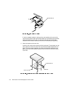
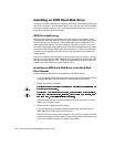
3. Remove the drive bracket from the chassis.
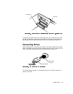
If any hard-disk drives are already installed in the bracket, disconnect the DC
power cable and interface cable from each drive.
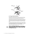
Remove the screw holding the drive bracket to the drive bay. Lift up on the drive
bracket to disengage it from the latch on the drive bay and the three hooks on the
front of the chassis (see Figure 9-9). Remove the bracket.