


Overview: Physical Memory Map
PmT1 and PmE1 User’s Manual 10002367-02
1-2
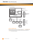
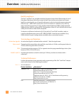
Figure 1-1: General System Block Diagram
PHYSICAL MEMORY MAP
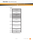
The physical memory map of the PmT1 and PmE1 is depicted in Fig. 1-2. Information on par-
ticular portions of the memory map can be found in later sections of this manual. See
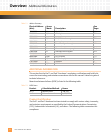
Tab le 1 -1 for a list of these references.
EIA232 Console
and Download
Serial Ports
CPU
MPC860P
PMC Connectors
P14
System Interface Unit (SIU)
Memory Controller
Internal
Bus Interface
Unit
External
Bus Interface
Unit
PCMCIA-ATA Interface
System Functions
Real-Time Clock
Power PC
Processor Core
32-Bit Bus
Communcations
Processor Module (CPM)
PMC Connectors
P11, P12
PCI Controller
PCI90x0
Serial
EEPROM
128 bytes
EEPROM
2 kilobytes
I C
2
1
A21/D32
A20/D8
A32/D32
32
PmT1 or PmE1
Channel 1
PmT1 or PmE1
Channel 2 or EIA422 Port
DRAM
16 megabytes
PCI
PCI
Flash/ROM
Socket
512 kilobytes