


TDM Interface:
PmT1 and PmE1 User’s Manual 10002367-02
6-2
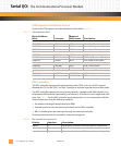
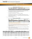
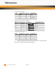
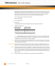
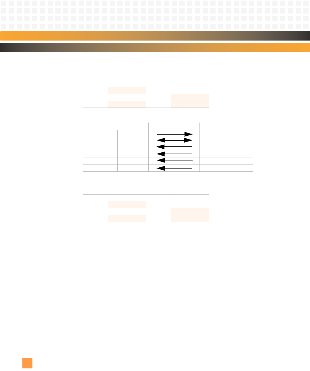
Table 6-2: T1E1 Signals from Transceiver, P1
Table 6-3: TDM to T1E1 Port Connections for TDMA (P2)
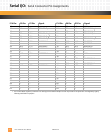
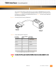
Table 6-4: T1E1 Signals from Transceiver, P2
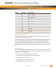
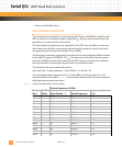
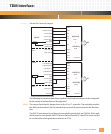
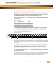
Fig. 6-1
and the signal list which follows indicate how the QUICC is connected to the
DS2151Q (T1) or DS2153Q (E1) interface controller.
P1 Pin: Signal Name: P1 Pin: Signal Name:
1 RRING 2 RTIP
3
no connect 4 TRING
5TTIP 6
no connect
7
no connect 8 no connect
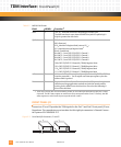
QUICC Pins to Transceiver: Direction: DS215xQ Function:
PA(9) L1TXDA TSER
PA(5) L1TCLKA TCLK
PC(5) L1TSYNCA TSYNC
PA(8) L1RXDA RSER
PA(7) L1RCLKA RCLK
PC(4) L1RSYNCA RSYNC
P2 Pin: Signal Name: P2 Pin: Signal Name:
1 RRING 2 RTIP
3
no connect 4 TRING
5TTIP 6
no connect
7
no connect 8 no connect