


10002367-02 PmT1 and PmE1 User’s Manual
5-1
Section 5
Serial I/O
The PmT1 and PmE1 module has six TTL serial ports that are supplied by the MPC860P Pow-
erQUICC™. The MPC860P supports the serial ports with the following features:
• Communications Processor Module (CPM), which includes a RISC controller, 224 buffer
descriptors, continuous mode transmission and reception on all serial channels, dual-
port RAM, fourteen serial DMA (SDMA) channels, and NMSI mode (each serial channel
can have its own pins)
• Four serial communication controllers (SCCs)
• Two serial management controllers (SMCs) for the console and download serial ports
• Four baud rate generators that are independent (i.e., can be connected to any SCC or
SMC), allow changes during operation, and have autobaud support
• Protocols in firmware for asynchronous/synchronous UARTs, HDLC, and SS7
For detailed descriptions of the MPC860P features and examples of how to implement
them, refer to the MPC860 PowerQUICC™ User’s Manual.
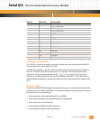
THE COMMUNICATIONS PROCESSOR MODULE
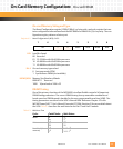
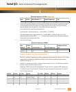
The physical base address of the MPC860P is FF00,0000
16
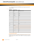
. The following table shows the
register block map for the CPM portion of the MPC860P. Please refer to the MPC860 Power-
QUICC™ User’s Manual for descriptions of the registers in each register block.
Table 5-1: MPC860P CPM Register Block Map
Physical Address (hex): Acronym: Register Block Name:
FF00,0930 — CPM Interrupt Control
FF00,0950 — Input/Output Port
FF00,0980 — CPM Timers
FF00,09C0 — Communication Processor
FF00,09F0 BRG Baud Rate Generators
FF00,0A00 SCC1 Serial Communications Controller 1
FF00,0A20 SCC2 Serial Communications Controller 2
FF00,0A40 SCC3 Serial Communications Controller 3
FF00,0A60 SCC4 Serial Communications Controller 4
FF00,0A82 SMC1 Serial Management Controller 1
FF00,0A9 SMC2 Serial Management Controller 2
FF00,0A82 — reserved
FF00,0AE0 SI Serial Interface