


TDM Interface:
10002367-02 PmT1 and PmE1 User’s Manual
6-3
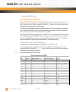
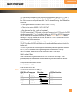
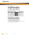
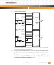
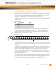
Figure 6-1: TDM and FDL Connectivity Diagram
The following list describes how these signals are used and how they are to be configured
for the variety of options that can be supported.
RCLK: The receive clock signal is always driven by the E1 or T1 controller. The controller provides
the ability to determine if the line interface has successfully synchronized to the line inter-
face.
The QUICC must always be configured to accept the receive clock on L1RCLKx. If the appli-
cation requires the transmit clock TCLK to be derived from RCLK, then RCLK can be routed
to an internal baud rate generator and driven as TCLK.
P2
P1
BRG02
BRG04
TDMA
QUICC
TDMB
FDLA
FDLB
L1TSYNCA (PC5)
L1RSYNCA (PC4)
L1TXDA (PA9)
L1RXDA (PA8)
L1RCLKA (PA7)
CLK1
CLK2 (PA6)
L1TCLKA (PA5)
BRG02/CLK3
TXD1 (PA14)
RXD1 (PA15)
L1TSYNCB (PC7)
L1RSYNCB (PC6)
L1TXDB (PA11)
L1RXDB (PA10)
L1RCLKB (PA2)
CLK6
BRG04 (PA1)
L1TCLKB (PA0)
CLK8
RXD2 (PA13)
CLK4 (PA4)
TXD2 (PA12)
TSYNC
RSYNC
TSER
RSER
RCLK
TCLK
TLINK
RLINK
TLCLK
RLCLK
or
PmE1
DS2153Q
PmT1
DS2151Q
Channel 1
TSYNC
RSYNC
TSER
RSER
RCLK
TCLK
TLINK
RLINK
TLCLK
RLCLK
or
PmE1
DS2153Q
PmT1
DS2151Q
Channel 0