


Serial I/O: UART Baud Rate Selection
PmT1 and PmE1 User’s Manual 10002367-02
5-6
• frames up to 8-kilobits long
UART BAUD RATE SELECTION
The clock sources for each SCC are defined in the SICR register (FF00,0AEC
16
) and for each
SMC are defined in the SIMODE register (FF00,0AE0
16
). Any one of four internal baud rate
generators or an external clock may be used.
The internal baud rate generators are contained in the CPM. They can deliver a maximum
baud rate at one half of the system clock rate and may be changed on-the-fly. Each baud
rate generator may be routed to multiple SCCs and SMCs.
The baud rate produced by a generator is set within the corresponding Baud Rate Generator
Control (BRGC) register (FF00,09F0 - 9FC
16
). The baud rate is calculated from the system
frequency (40 MHz) and the values stored in the BRGC register, and depends on whether
the serial controller is operating in asynchronous or synchronous mode.
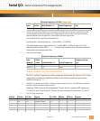
The formula for the asynchronous baud rate is:
async baud rate = (system frequency) ÷ ((clock divider +1) x (Div16) x 16)
The clock divider value is stored in bits (12:1) of the BRGC. The Div16 value (1 or 16) is
selected with bit 0 of the BRGC.
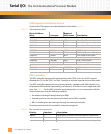
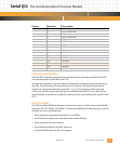
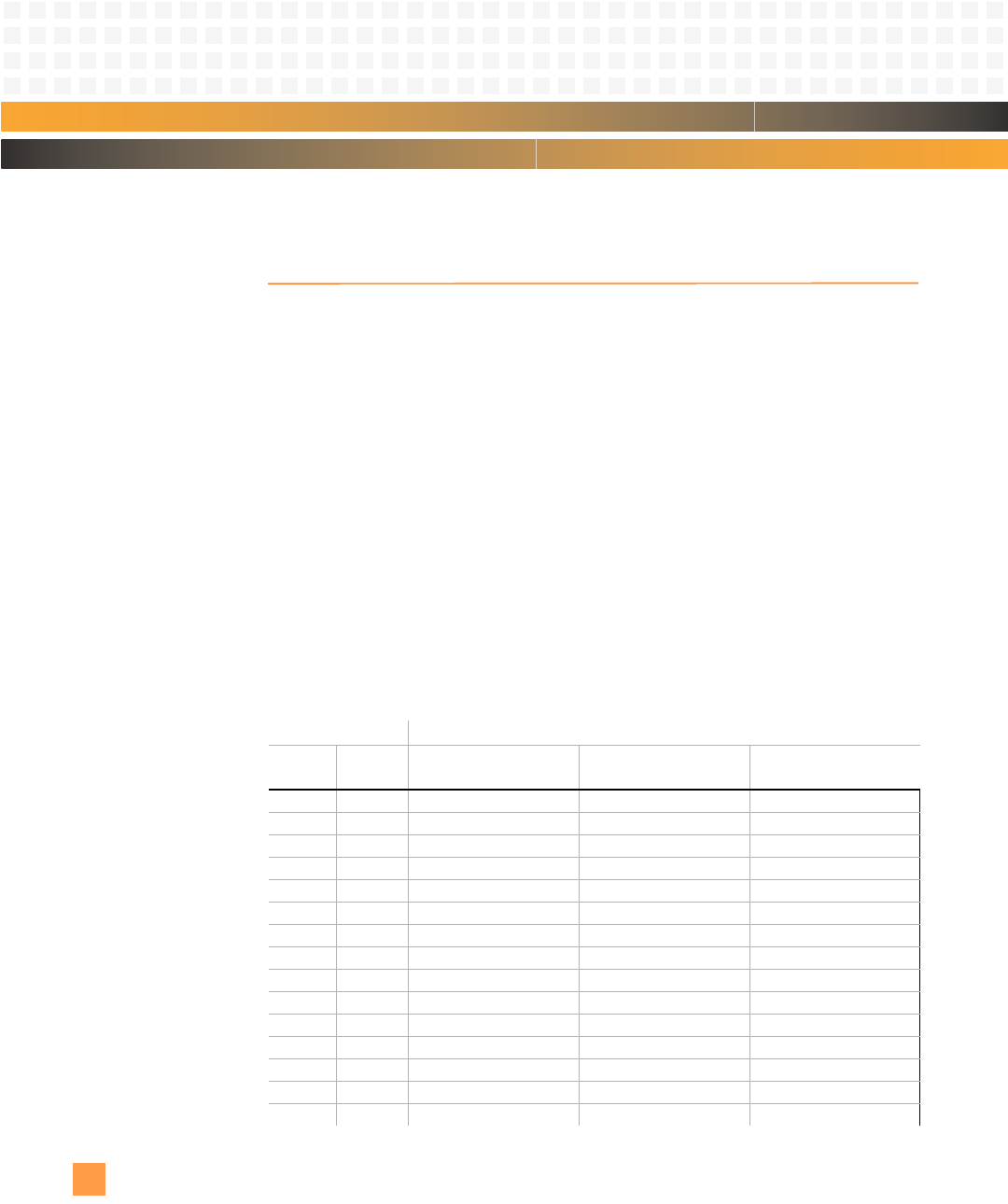
Ta ble 5 - 4 lists the clock divider and Div16 values associated
with typical asynchronous baud rates.
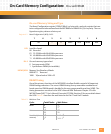
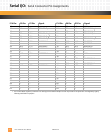
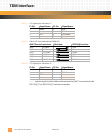
Table 5-4: Asynchronous Baud Rates (16X oversample)
System Frequency=40 MHz
Baud
Rate:
Div16
Value: Clock Divider + 1: Actual Frequency:
Frequency Error
(%):
50 16 3125 50 0.0
75 16 2083 75 0.0
150 16 1041 150.1 0.0
300 16 521 299.9 0.0
600 1 4167 599.95 0.0
1200 1 2083 1200.2 0.0
2400 1 1042 2399.2 0.0
4800 1 521 4798.5 0.0
9600 1 260 9615.4 0.2
19200 1 130 19230.8 0.2
38400 1 65 38461.5 0.2
57600 1 43 58139.5 0.9
64000 1 39 64102.6 0.2
115200 1 22 113636.4 1.4
56000 1 45 55555.6 0.8