PMC/PCI Interface: PMC Connector Pin Assignments
PmT1 and PmE1 User’s Manual 10002367-02
7-10
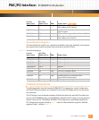
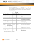
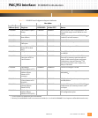
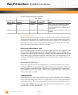
PCI Bus Control Signals
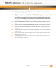
The following signals for the PCI interface are available on connectors P11 and P12. Refer to
the PCI specification for detailed usage of these signals. All signals are bi-directional unless
stated otherwise.
Note: A sustained tri-state line is driven high for one clock cycle before float.
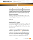
AD00-AD31: ADDRESS and DATA bus (bits 0-31) tri-state lines are used for both address and data han-
dling. A bus transaction consists of an address phase followed by one or more data phases.
BUSMODE1*-4*: The PmT1 and PmE1 modules assert BUSMODE1* to indicate to the baseboard that it is
present and capable of performing PCI protocols. The baseboard uses BUSMODE2*-4* to
indicate that it is PCI compatible.
C/BE0* -C/BE3*: BUS COMMAND and BYTE ENABLES tri-state lines have different functions depending on the
phase of a transaction. During the address phase of a transaction these lines define the bus
command. During a data phase the lines are used as byte enables.
CLK: CLOCK input signal to the PmT1 and PmE1 provides timing for PCI transactions.
DEVSEL*: DEVICE SELECT sustained tri-state signal indicates when a device on the bus has been
selected as the target of the current access.
FRAME*: CYCLE FRAME sustained tri-state line is driven by the current master to indicate the begin-
ning of an access, and continues to be asserted until transaction reaches its final data phase.
GNT*: GRANT input signal indicates that access to the bus has been granted to a particular master.
Each master has its own GNT*.
IDSEL: INITIALIZATION DEVICE SELECT input signal acts as a chip select during configuration read
and write transactions.
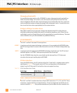
INTA*: PMC INTERRUPT A input line is used by the PmT1 and PmE1 to interrupt the baseboard.
IRDY*: INITIATOR READY sustained tri-state signal indicates that the bus master is ready to com-
plete the data phase of the transaction.
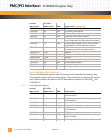
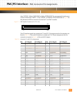
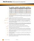
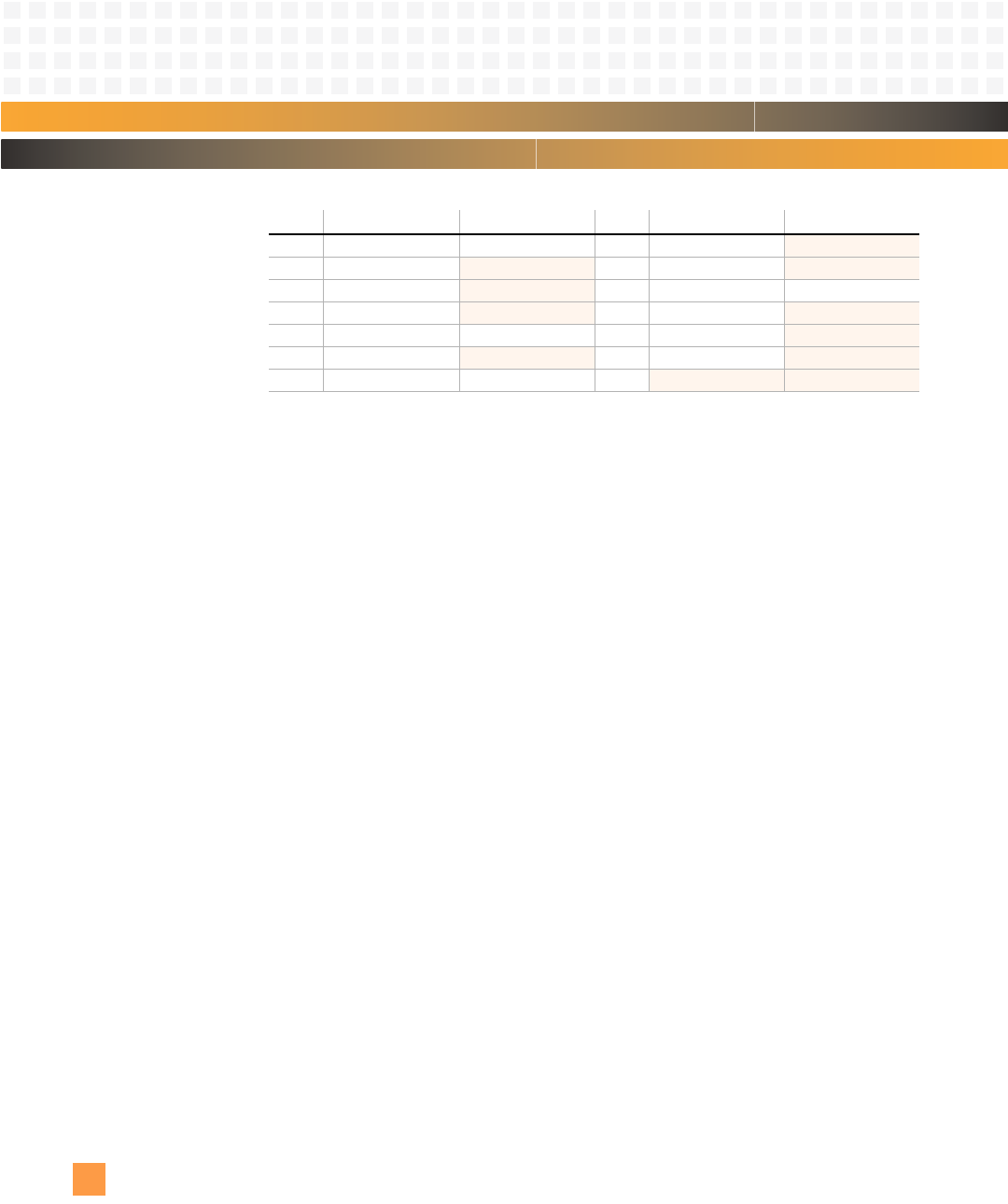
51 GND AD07 52 C/BE0* no connect
53 AD06
no connect 54 AD05 no connect
55 AD04
no connect 56 GND GND
57 +5V
no connect 58 AD03 no connect
59 AD02 GND 60 AD01
no connect
61 AD00
no connect 62 +5V no connect
63 GND GND 64
no connect no connect
Pin: P11 Signal: P12 Signal: Pin: P11 Signal: P12 Signal:


