PMC/PCI Interface: PMC Connector Pin Assignments
10002367-02 PmT1 and PmE1 User’s Manual
7-9
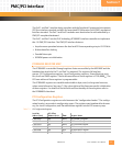
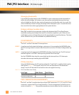
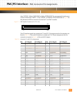
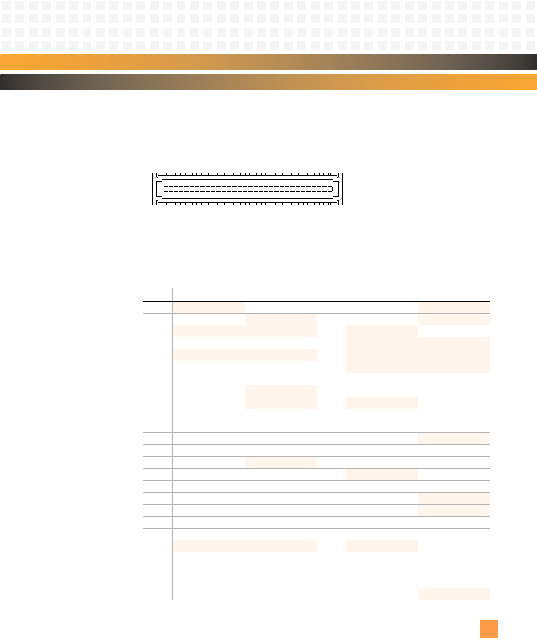
Amp 120534-1, Molex 53483-0649 or Molex 53508-0648. The recommended mating con-
nectors include Amp 120521-1, Amp 120528-1, and Molex 52763-0649. Refer to
Fig. 2-1 for
the placement of these connectors on the PmT1 and PmE1 module.
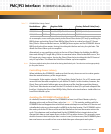
Figure 7-1: PMC Interface Connectors (P11, P12, P14)
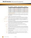
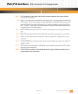
The PCI interface signals are routed out P11 and P12. Pin assignments for this interface are
listed in
Tab le 7 -9 . The serial I/O interface is routed out P14. The pin assignments for this
connector are given in
Tab le 5 -6 of the serial I/O chapter.
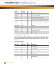
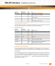
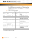
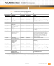
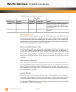
Table 7-9: Connector P11 and P12 Pin Assignments
Pin: P11 Signal: P12 Signal: Pin: P11 Signal: P12 Signal:
1 no connect +12V 2 -12V no connect
3GND
no connect 4 INTA* no connect
5
no connect no connect 6 no connect GND
7BUSMODE1*GND 8
no connect no connect
9
no connect no connect 10 no connect no connect
11 GND BUSMODE2* 12
no connect no connect
13 CLK RST* 14 GND BUSMODE3*
15 GND
no connect 16 GNT* BUSMODE4*
17 REQ*
no connect 18 no connect GND
19 +5V AD30 20 AD31 AD29
21 AD28 GND 22 AD27 AD26
23 AD25 AD24 24 GND
no connect
25 GND IDSEL 26 C/BE3* AD23
27 AD22
no connect 28 AD21 AD20
29 AD19 AD18 30
no connect GND
31 +5V AD16 32 AD17 C/BE2*
33 FRAME* GND 34 GND
no connect
35 GND TRDY* 36 IRDY*
no connect
37 DEVSEL* GND 38 +5V STOP*
39 GND PERR* 40 LOCK* GND
41
no connect no connect 42 no connect SERR*
43 PAR C/BE1* 44 GND GND
45 +5V AD14 46 AD15 AD13
47 AD12 GND 48 AD11 AD10
49 AD09 AD08 50 +5V
no connect
1
2
63
64


