PMC/PCI Interface: PCI9060ES Initialization
PmT1 and PmE1 User’s Manual 10002367-02
7-4
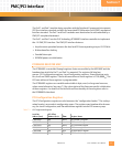
The serial EEPROM may be reprogrammed to configure the PCI bridge in other ways. Bits
(27:24) of the PCI9060ES EEPROM control register (C100,00EC
16
) are used for reading and
writing the EEPROM. Refer to the NS93CS46 data sheet listed in
Tab le 1 -5 for a description of
the EEPROM’s programming instructions, and the PCI9060ES data sheet for the sequence
in which the data is stored.
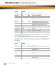
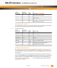
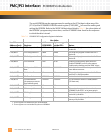
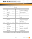
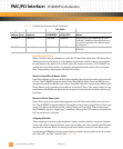
Table 7-4: PCI9060ES PCI Configuration Register Initialization
Hex Value
Local Bus
Address (hex): Register:
at the
PCI9060ES:
byte-swapped
at the CPU: Notes:
C100,0000
1
1. These registers are initialized by the serial EEPROM.
PCI Configuration ID 1223 2312 This read-only register contains Emerson’s
vendor ID.
C100,0002
1
PCI Configuration ID 0004 0400 This read-only register contains the PmT1
device ID.
C100,0002
1
PCI Configuration ID 0005 0500 This read-only register contains the PmE1
device ID.
C100,0004
2
2. These registers are not initialized by the serial EEPROM.
PCI Command 0147 4701 Enable I/O and memory space accesses.
Enable PCI9060ES to act as a bus master.
Enable parity checking and the SERR* driver.
C100,0030
2
PCI Expansion ROM
Base
00000000 00000000 Address decode enable and expansion ROM
base address accesses.
C100,0008
1
PCI Revision ID 01 01 This read-only register contains the PmT1
and PmE1’s revision number.
C100,0009
1
PCI Class Code 0B20000 00200B No interface is defined.
C100,0018
2
PCI Base Address
(for memory access to
local address space)
xxxxxxxx xxxxxxxx PCI-to-local base address is 0000,0000
16
.
(PCI host sets)
C100,003C
1
PCI interrupt Line 00 00 —
C100,003D
1
PCI Interrupt Pin 01 01 This read-only register indicates that the
PCI9060ES uses INTA* as its interrupt pin.
C100,003E
1
PCI Min_Gnt 00 00 This read-only register specifies a burst
period of 0 μseconds.
C100,003F
1
PCI Max_Lat 00 00 This read-only register specifies a maximum
latency of 0 μseconds.


