


Central Processing Unit: Optional BDM Header
PmT1 and PmE1 User’s Manual 10002367-02
3-6
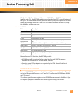
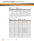
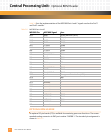
Tab le 3 -6 lists the implementation of the MPC860 Port A and C signals used on the PmT1
and PmE1 module.
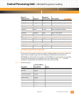
Table 3-6: MPC860P Ports A and C
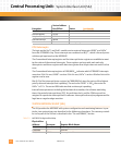
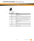
OPTIONAL BDM HEADER
An optional 10-pin header (P3) is available for examining processor functions. The recom-
mended mating connector is AMP part number 746288-1. The standard pin assignment is
shown in
Tab le 3 -7 .
MPC860 Pin: MPC860 Signal: Use:
PA15 RXD1 Facility Data Link (FDL A)
PA14 TXD1 FDL(A)
PA13 RXD2 FDL(B)
PA12 TXD2 FDL(B)
PA11 L1TXDB TDMB
PA10 L1RXDB TDMB
PA9 L1TXDA TDMA
PA8 L1RXDA TDMA
PA7 CLK1/L1RCLKA TDMA
PA6 CLK2 TDMA
PA5 BRGO2 TDMA
PA4 CLK4 FDL
PA3
reserved —
PA2 CLK6/L1RCLKB TDMB
PA1 BRGO4 TDMB
PA0 CLK8/L1TCLKB TDMB
PC15 — Management Data Interface (MDI)
PC14 — MDI
PC13 — MDI
PC12
reserved —
PC11
reserved —
PC10
reserved —
PC9
reserved —
PC8
reserved —
PC7 L1TSYNCB TDMB
PC6 L1RSYNCB TDMB
PC5 L1TSYNCA TDMA
PC4 L1RSYNCA TDMA
PC3
reserved —