10002367-02 PmT1 and PmE1 User’s Manual
v
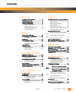
Contents
1Overview
Components and Features . . . . . . . . . . . 1-1
Functional Overview . . . . . . . . . . . . . . . . 1-1
Physical Memory Map . . . . . . . . . . . . . . . 1-2
Additional Information . . . . . . . . . . . . . . 1-4
Product Certification. . . . . . . . . . . . .1-4
RoHS Compliance. . . . . . . . . . . . . . . .1-6
Terminology and Notation. . . . . . . .1-6
Technical References. . . . . . . . . . . . .1-6
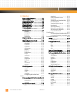
2Setup
Electrostatic Discharge . . . . . . . . . . . . . . 2-1
PmT1 and PmE1 Circuit Board . . . . . . . . 2-1
Connectors . . . . . . . . . . . . . . . . . . . . .2-4
Installation. . . . . . . . . . . . . . . . . . . . . . . . . 2-4
PmT1 and PmE1 Setup . . . . . . . . . . . . . . 2-5
Power Requirements. . . . . . . . . . . . .2-5
Environmental Considerations . . . .2-6
Reset Methods . . . . . . . . . . . . . . . . . . . . . 2-6
Troubleshooting. . . . . . . . . . . . . . . . . . . . 2-6
Technical Support . . . . . . . . . . . . . . .2-7
Product Repair . . . . . . . . . . . . . . . . . .2-8
3 Central Processing Unit
MPC860P Initialization . . . . . . . . . . . . . . 3-1
MPC860P Exception Handling . . . . . . . . 3-3
CPU Interrupts . . . . . . . . . . . . . . . . . .3-4
System Interface Unit (SIU). . . . . . . . . . . 3-4
Timebase Counter . . . . . . . . . . . . . . .3-5
Decrementer Counter. . . . . . . . . . . .3-5
Software Reset . . . . . . . . . . . . . . . . . . . . . 3-5
MPC860 Parallel Port configuration . . . 3-5
Optional BDM Header . . . . . . . . . . . . . . . 3-6
4 On-Card Memory
Configuration
Socketed Flash . . . . . . . . . . . . . . . . . . . . . 4-1
I2C EEPROM. . . . . . . . . . . . . . . . . . . . . . . . 4-1
I2C EEPROM Operation. . . . . . . . . . .4-2
Emerson Memory Map . . . . . . . . . . .4-2
On-card DRAM . . . . . . . . . . . . . . . . . . . . . 4-2
On-card Memory Sizing and Type. .4-3
DRAM Timing . . . . . . . . . . . . . . . . . . .4-3
5 Serial I/O
The Communications Processor Module5-1
CPM Register Initialization Format. 5-2
RISC Controller. . . . . . . . . . . . . . . . . . 5-2
CPM Interrupt Handling . . . . . . . . . . 5-3
Dual-Port RAM . . . . . . . . . . . . . . . . . . 5-3
General Purpose Timers . . . . . . . . . . 5-4
Independent DMA (IDMA) Channels5-4
Serial DMA (SDMA) Channels . . . . . 5-4
MPC860P Serial Interface . . . . . . . . . . . . .5-4
Serial Communication Controllers
(SCC) . . . . . . . . . . . . . . . . . . . . . . . . . . . . . . . . . . 5-5
Serial Management Controllers
(SMC). . . . . . . . . . . . . . . . . . . . . . . . . . . . . . . . . . 5-5
Time Slot Assigner (TSA) . . . . . . . . . 5-5
UART Baud Rate Selection . . . . . . . . . . . .5-6
Serial Connector Pin Assignments . . . . .5-7
6TDM Interface
The T1 or E1 Line Interface . . . . . . . . . . . .6-4
Configuring the T1 or E1 Interface . . . . .6-5
The T1 FDL Interface . . . . . . . . . . . . . . . . .6-5
The Management Data Interface (MDI) .6-7
Front Panel I/O . . . . . . . . . . . . . . . . . . . . . .6-8
7PMC/PCI Interface
PCI9060ES Register Map. . . . . . . . . . . . . .7-1
PCI Configuration Registers. . . . . . . 7-1
Local Configuration Registers . . . . . 7-2
Shared Runtime Registers . . . . . . . . 7-3
PCI9060ES Initialization . . . . . . . . . . . . . .7-3
Deadlocked Cycles . . . . . . . . . . . . . . 7-6
Retries on Local Direct Master
Cycles . . . . . . . . . . . . . . . . . . . . . . . . . . . . . . . . . .7-6
Retries on Direct Slave Cycles. .7-6
Assigning Priorities. . . . . . . . . . .7-6
Controlling Access Latency . . . . . . . 7-7
Avoiding the PCI9060ES Phantom
Read. . . . . . . . . . . . . . . . . . . . . . . . . . . . . . . . . . . 7-7
Managing Bandwidth . . . . . . . . . . . . 7-8
Bridge to Bridge Considerations. . . 7-8
PCI Interrupts . . . . . . . . . . . . . . . . . . . . . . .7-8
PCI Bus Interface . . . . . . . . . . . . . . . . 7-8
PMC Connector Pin Assignments . . . . . .7-8
PCI Bus Control Signals. . . . . . . . . . 7-10


