


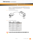


TDM Interface: Configuring the T1 or E1 Interface
10002367-02 PmT1 and PmE1 User’s Manual
6-5
CONFIGURING THE T1 OR E1 INTERFACE
The PmT1 and PmE1 framers have typical configuration settings for operation. The typical
operational mode for T1 is:
• Transmit/receive ESF mode enabled
• Line build-out set to 133 feet/0 dB (DSX-1/CSU applications)
• B8ZS encoding enabled
• Jitter attenuator enabled
The typical operational mode for E1 is:
• HDB3 enabled
•CRC4 enabled
• CCS mode enabled (time slot 16 is available for use)
• Automatic E-bit insertion enabled
• Automatic resync enabled
• Automatic remote alarm generation enabled
• Jitter attenuator enabled
• Line build-out set to 120 ohms
• Si bits are otherwise managed by the framer device
• Error counters change every 500 frames (about once per second). The error count only
pertains to the second before the register was polled.
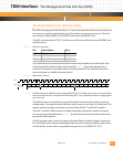
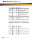
THE T1 FDL INTERFACE
The Facility Data Link (FDL) is the mechanism used by a T1 port to communicate operating
statistics. The FDL consists of one bit for every other frame of data, or a 4-KHz serial data
port. For most applications the FDL remains inactive waiting for commands. The DS2151Q
uses the HDLC protocol to transfer information to and from the FDL.
Note: The Facility Data Link is currently not available for use on the PmT1 due to latency of the MDI interface.
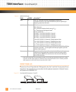
The PmT1 support for the FDL varies depending on the application requirements. Normally
the FDL can be accessed via the FDL transmit and receive registers inside the DS2151Q T1
controller. The DS2151Q can be configured to generate interrupts when the receiver goes
full, transmitter goes empty, and when a particular pattern is detected at the receiver. Use
the SI mode register to set up transmit and receive frame sync delays (0-3 clocks) to mask
the F-bit in T1 applications (RFSDA = 1 for DS2151Q and 0 for DS2153Q).