


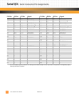
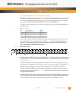
Serial I/O: Serial Connector Pin Assignments
PmT1 and PmE1 User’s Manual 10002367-02
5-8
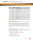
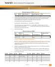
13 — — — 14 B6 A7 GND
15 A6 C8 TDM#2 TxTip
1
16 E7 A8 TDM#2 TxRing
1
17 — — — 18 C7 A9 TDM#2 RxTip
1
19 B7 C10 TDM#2 RxRing
1
20 A7 A10 TDM#1 TxTip
1
21 E6 C11 TDM#1 TxRing
1
22 — — —
23 C8 C12 TDM#1 RxTip
1
24 B8 A12 TDM#1 RxRing
1
25 A8 C13 RS422 TXD-* 26 E12 A13 RS422 TXD+
27 — — — 28 C12 A14 RS422 RXD+
29 B12 C15 RS422 RXD-* 30 A12 A15 RS422 RTS+
31 E13 C16 RS422 RXCLK+ 32 D13 A16 RS422 CTS+
33 ——— 34———
35 A13 C18 RS422 RTS-* 36 E14 A18 GND
37 ——— 38———
39 — — — 40 A14 A20 RS422 RXCLK-*
41 ——— 42———
43 — — — 44 B15 A22 RS422 TXCLK-*
45 A15 C23 RS422 TXCLK+ 46 E16 A23 RS422 CTS-*
47 ——— 48———
49 ——— 50———
51 ——— 52———
53 ——— 54———
55 ——— 56———
57 ——— 58———
59 ——— 60———
61 ——— 62———
63 ——— 64———
1. All xTIP and xRING signals are routed to P14 directly from the Dallas interface and do not provide circuit protection. See Regulatory Agency
Warnings and Notices in preface.
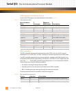
P14 Pin: P0 Pin: P2 Pin: Signal: P14 Pin: P0 Pin: P2 Pin: Signal: