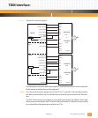
Serial I/O: MPC860P Serial Interface
PmT1 and PmE1 User’s Manual 10002367-02
5-4
General Purpose Timers
The general purpose timers can be configured as four 16-bit or two 32-bit identical timers.
The best resolution of the time is one clock cycle, which translates to 25 nanoseconds at 40
MHz. The maximum period is 268,435,456 cycles, translating to 6.7 seconds at 40 MHz.
Independent DMA (IDMA) Channels
The MPC860P has two IDMA channels which may be programmed by the user to transfer
data between any combination of memory and I/O. The IDMA supports 32-bit data and
addressing, dual or single address modes, and three buffer modes (single, auto, and buffer
chaining). The theoretical maximum data rate of the IDMA with a local bus speed of 25 MHz
is 50 MB/second.
Serial DMA (SDMA) Channels
The MPC860P has fourteen SDMA channels dedicated to the transmit/receive channels of
the serial controllers. Data from the serial controllers may be routed either to external RAM
or to internal dual-port RAM. When transfers use the internal dual-port RAM, other opera-
tions may occur simultaneously on the PmT1 and PmE1 local bus.
MPC860P SERIAL INTERFACE
Several types of popular serial protocols are available on the PmT1 and PmE1. Please refer
to the MPC860 PowerQUICC™ User's Manual for more detail on these supported protocols.
UART: The universal asynchronous receiver transmitter protocol is the defacto standard for com-
municating low-speed data between equipment. The most popular of these is the EIA-232
standard. EIA-232 specifies standard baud rates, handshaking protocols, and mechani-
cal/electrical details. Other popular standards include EIA-422 and EIA-485, which offer fea-
tures such as longer line lengths and multidrop support.
The UART also supports synchronous mode, where a clock is provided with each bit. Syn-
chronous UART mode can provide faster data transfers, because there is no need to over-
sample the data bits.
HDLC: HDLC is one of the most common layer 2 protocols (of the seven-layer OSI model). HDLC
protocol consists of a framing structure which is synchronously transferred. Therefore,
HDLC relies on the physical layer (i.e., SI with TSA) to provide a method of clocking and syn-
chronizing the transmitter/receiver. Each of the four SCCs can function as an HDLC control-
ler. The SCC outputs can then be routed directly to the external pins, or connected to one of
two TDM channels via the TSA.


