


On-Card Memory Configuration: On-card DRAM
PmT1 and PmE1 User’s Manual 10002367-02
4-4
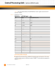
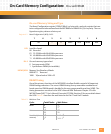
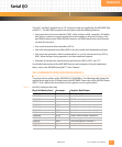
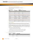
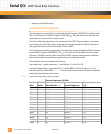
For non-burst cycles, the number in the “Total Clocks” column of Tab l e 4- 3 is the total num-
ber of CPU clock cycles required to complete the transfer, and the number in the “Wait
States” column is the number of wait states per cycle.
For burst cycles, the number in the “Total Clocks” column of
Ta bl e 4 -3 is the total number of
CPU clocks for the first access of the four long-word burst, plus the number of clocks for the
second, third, and fourth cycles. The number in the “Wait States” column is the number of
wait states for each of the four accesses.
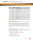
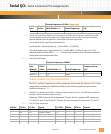
Burst Write (4
accesses)
7
1
5
2
2-1-1-1
1
2-1-1-1
2
1. At 40 MHz local bus speed.
2. At 33 MHz local bus speed.
Cycle: Total Clocks: Wait States: (continued)