


Paper Feed Frame
1 Remove the Printer Covers.
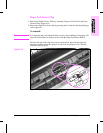
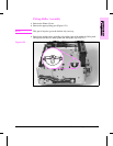
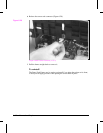
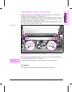
2 Remove the Pickup Roller Assembly (Figures 6-23 through 6-24).
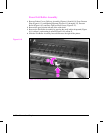
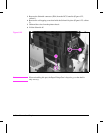
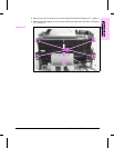
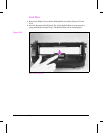
3 Release the connectors from the Laser/Scanner, Top Cover/EP Cartridge Sensor
(PS203), Switch 101, Front Control Panel (Figure 6-26). Disconnect the Solenoid
from the DC Controller at J204 (Figure 6-22, callout 1).
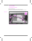
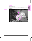
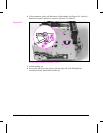
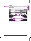
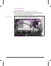
Paper Feed Frame Removal
Figure 6-26
6 - 30 Removal and Replacement