


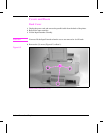
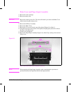
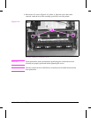
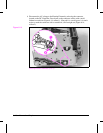
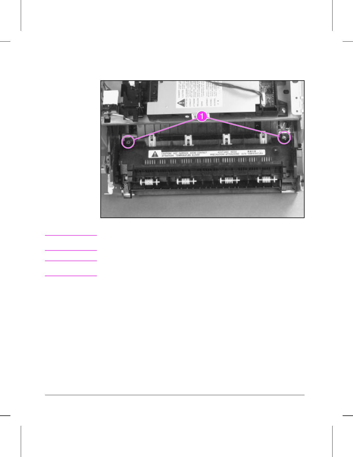
3 Remove the (2) screws (Figure 6-10, callout 1). Once the screws have been
removed, rotate the rear of the assembly up and lift it out of the printer.
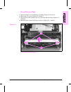
Delivery Assembly Removal (2 of 2)
Caution
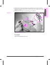
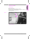
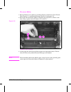
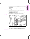
Upon replacement, make certain that the positioning pins on the bottom of the
assembly are properly positioned before tightening the screws.
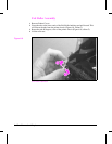
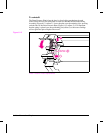
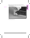
Note
The tabs on the front end of the Delivery Assembly must fit under the sheet metal
fuser plate below.
Figure 6-10
6 - 14 Removal and Replacement