


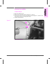
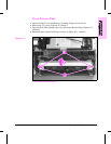
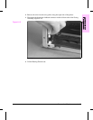
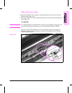
4 Remove the wire from the wire guides along the right-side of the printer.
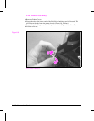
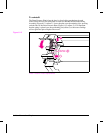
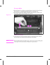
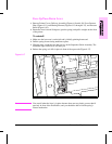
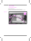
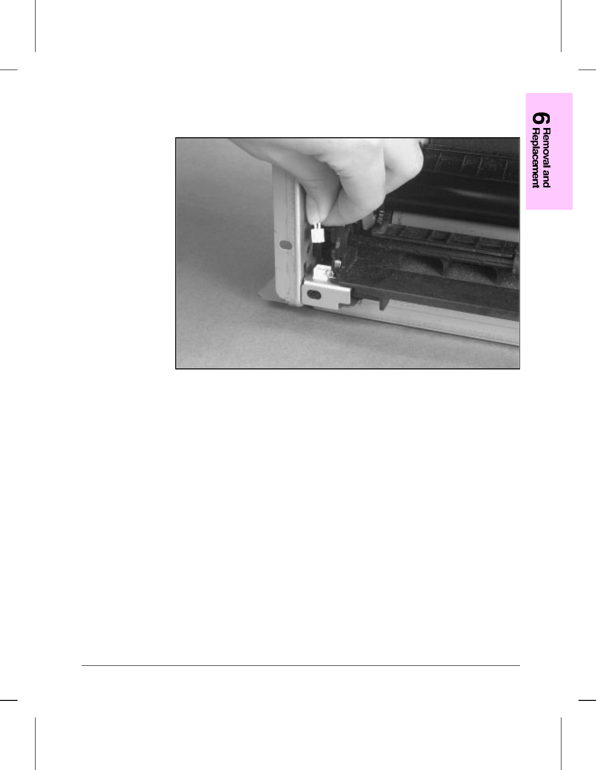
5 Disconnect the thermistor feedback connector in the left front side of the Fusing
Assembly (Figure 6-15).
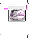
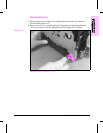
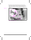
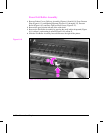
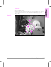
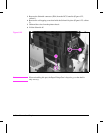
Heating Element Removal (3 of 3)
6 Lift the Heating Element out.
Figure 6-15
Removal and Replacement 6 - 19