


NOTE: The cover release lever also disengages the memory carrier assembly cover for
removal.
You can have the memory carrier assembly cover in place while servicing any components
except for the memory carrier assembly and the processor board assembly.
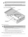
4. Slide the cover toward the rear of the server until the tabs release from the slots in the chassis.
5. Lift the cover off the chassis.
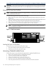
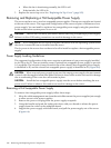
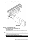
Figure 6-3 Removing and Replacing the Top Cover
Memory Carrier
Assembly Cover
Top Cover
Cover Release
Lever (Latch/Unlatch)
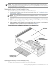
Replacing the Top Cover
NOTE: Replace the memory carrier assembly cover before replacing the top cover.
To replace the top cover, follow these steps:
1. Ensure the cover release lever is in the open position (Figure 6-3).
2. Align the tabs of the top cover with the corresponding slots in the chassis and insert the tabs
into the slots.
3. Slide the cover forward until it is flush with the front of the chassis; push firmly.
4. Push the cover release lever down into the latched position (Figure 6-3).
5. Lock the cover release lever by turning the cam approximately 90 degrees clockwise.
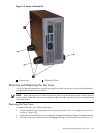
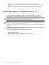
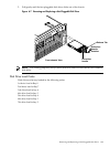
Removing and Replacing the Memory Carrier Assembly Cover
Access to the memory carrier assembly is required for upgrades and repair of the server memory.
182 Removing and Replacing Server Components