


Memory Installation Conventions
Before installing memory, read and understand the following memory installation conventions:
• Supported DIMM sizes and memory configurations
• DIMM load order
• DIMM slot IDs
Supported DIMM Sizes and Memory Configurations
The standard server configuration includes an 8-DIMM memory carrier which contains two
4-DIMM memory boards. An optional, high-capacity memory configuration is also available: a
24-DIMM memory carrier containing two 12-DIMM memory boards.
System DIMMs seat onto the memory boards. The minimum server configuration requires at
least one memory pair in the 8-DIMM memory carrier, and one memory quad (group of four
DIMMs) in the 24-DIMM memory carrier.
The following are the supported DIMM sizes for the server:
• 512 MB
• 1 GB
• 2 GB
• 4 GB
Table 3-4 lists the supported memory configurations for the server.
Table 3-4 Supported Memory Configurations
Maximum Memory
Configuration
Minimum Memory
Configuration
Memory Boards InstalledMemory Carrier Type
32 GB (eight 4 GB DIMMs)2-GB (one pair: two 1-GB
DIMMs)
Two 4-DIMM memory
boards
8-DIMM memory carrier
(standard)
96 GB (24x4 GB DIMMs)2 GB (one quad: four 512
MB DIMMs)
Two 12-DIMM memory
boards
24-DIMM memory carrier
(optional, high-capacity)
Memory Load Order
When installing memory, use a minimum of one pair in the 8-DIMM memory carrier, and one
quad in the 24-DIMM memory carrier, of like-sized DIMMs. Insert additional DIMMs into the
memory carriers in the next available pair or quad, in order of capacity from largest to smallest.
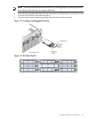
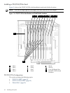
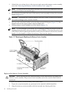
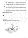
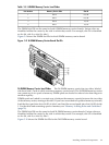
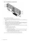
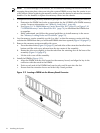
Install DIMMs into the appropriate slots on the memory carrier board; each slot has a unique
ID. Use Figure 3-9 and Figure 3-10 to determine where to install DIMMs on the memory carrier
board.
CAUTION: Do not mix DIMM sizes or types within a pair or quad. Load DIMM pairs and quads
in order of capacity from largest to smallest. For example, if you have a quad of 2 GB DIMMs
and a quad of 1 GB DIMMs, install the quad of 2 GB DIMMs first.
Failure to observe these cautions results in system degradation or failure
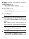
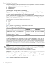
8-DIMM Memory Carrier Load Order The 8-DIMM memory carrier has two sides labeled side
0 and side 1, each of which contains a memory carrier board. The 8-DIMM memory carrier can
contain one to four pairs of memory. Pairs of memory are divided equally between the two sides
of the memory carrier. For example, if you have two pairs of memory to install, load two DIMMs
in slots 0A and 0B of side 0, and load two DIMMs in slots 0A and 0B of side 1.
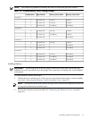
Table 3-5 lists the 8-DIMM memory carrier load order.
68 Installing the System