


NOTE: Assembly side 0 is on the left, and assembly side 1 is on the right as viewed from
the front of the chassis.
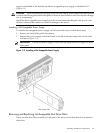
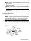
3. Slide the memory carrier assembly into the chassis until it begins to seat into the socket
located on the processor board.
CAUTION: Do not apply excessive force when closing the extraction handles and seating
the memory carrier assembly into the socket on the processor board. Manipulate the extraction
handles with care. Failure to observe these cautions can result in damage to the extraction
handles and other server components.
4. Rotate the extraction handles inward and press the handles straight down until they snap
into the locked position.
5. Replace the memory carrier assembly cover and latch the top cover release lever closed. See
“Replacing the Memory Carrier Assembly Cover” (page 58).
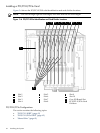
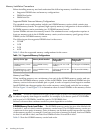
Installing System Memory DIMMs
System memory or DIMMs are located on a pair of memory boards inside the memory carrier
assembly.
WARNING! Ensure that the system is powered off and all power sources have been disconnected
from the server prior to performing this procedure.
Voltages are present at various locations within the server whenever an ac power source is
connected. This voltage is present even when the main power switch is in the off position.
Failure to observe this warning can result in personal injury or damage to equipment.
CAUTION: Observe all ESD safety precautions before attempting this procedure. Failure to
follow ESD safety precautions can result in damage to the server.
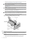
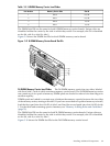
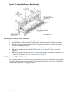
Figure 3-7 (page 66) shows the memory carrier assembly removed from the chassis.
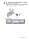
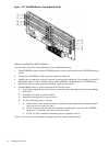
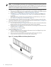
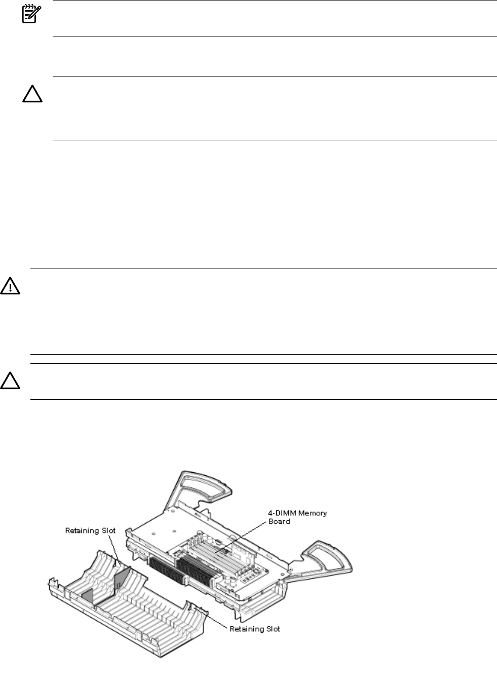
Figure 3-8 shows the memory carrier with the side cover removed.
Figure 3-8 Memory Carrier Assembly with Side Cover Removed
Installing Additional Components 67