


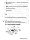
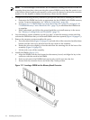
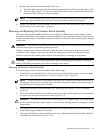
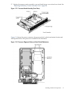

7. Replace the memory carrier assembly side cover.
a. Insert the side cover tabs into the retaining slots at the base of the assembly (Figure 3-8).
b. Insert the tabs (Figure 3-8) into the slots on both sides of the extraction handle release
button until the side cover snaps into place.
NOTE: To install DIMMs into slots on the other side of the memory carrier, turn the carrier
over to the opposite side (side 0 or side 1) and repeat the installation procedure.
8. Replace the memory carrier assembly and latch the top cover release lever. See “Replacing
the Memory Carrier Assembly” (page 66).
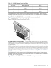
Removing and Replacing the Processor Board Assembly
The processor board assembly holds one or two dual-core Itanium processors and is located
beneath the disk drives and memory carrier assembly in the bottom service bay. The processor
board is mounted onto a removable carrier tray which is retained in the service bay by a hinged
access door.
WARNING! Ensure that the system is powered off and all power sources have been disconnected
from the server prior to performing this procedure.
Voltages are present at various locations within the server whenever an ac power source is
connected. This voltage is present even when the main power switch is in the off position.
Failure to observe this warning can result in personal injury or damage to equipment.
CAUTION: Observe all ESD safety precautions before attempting this procedure. Failure to
follow ESD safety precautions can result in damage to the server.
Removing the Processor Board Assembly
To remove the processor board assembly, follow these steps:
1. Unlatch the cover release lever on the top cover and remove the memory carrier assembly
cover. See “Removing the Memory Carrier Assembly Cover” (page 57).
NOTE: You do not need to fully remove the top cover to service this component; however,
the top cover release lever must be open. You must remove the memory carrier because it
attaches directly to the processor board.
2. Remove the memory carrier assembly. See “Removing the Memory Carrier Assembly”
(page 65).
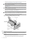
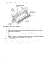
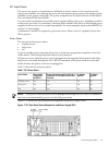
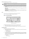
3. Press the button located on top of the bezel directly in front of the memory carrier assembly
to release the processor board access door (Figure 3-12).
CAUTION: The processor board access door opens at a 30 degree angle. Do not force the
door to open to a greater angle. Failure to observe this warning results in damage to server
components.
4. Use the processor board assembly access door as a handle and gently slide the assembly out
of the chassis approximately six inches.
5. Grasp the handholds on the assembly carrier tray with both hands and carefully slide the
assembly out of the chassis (Figure 3-12).
Installing Additional Components 73