


NOTE: The extraction handles latch into the open position with an audible click.
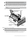
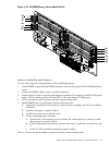
6. Pull the extraction handles to lift the memory carrier assembly out of the chassis (Figure 6-12).
NOTE: To avoid damage to the extraction handles, HP recommends rotating the handles
inward and snapping them into the locked position when servicing the system DIMMs or
any time the carrier is out of the chassis. Before replacing the memory carrier, press the
button to release the extraction handles. Use the handles to replace the memory carrier into
the chassis.
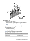
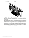
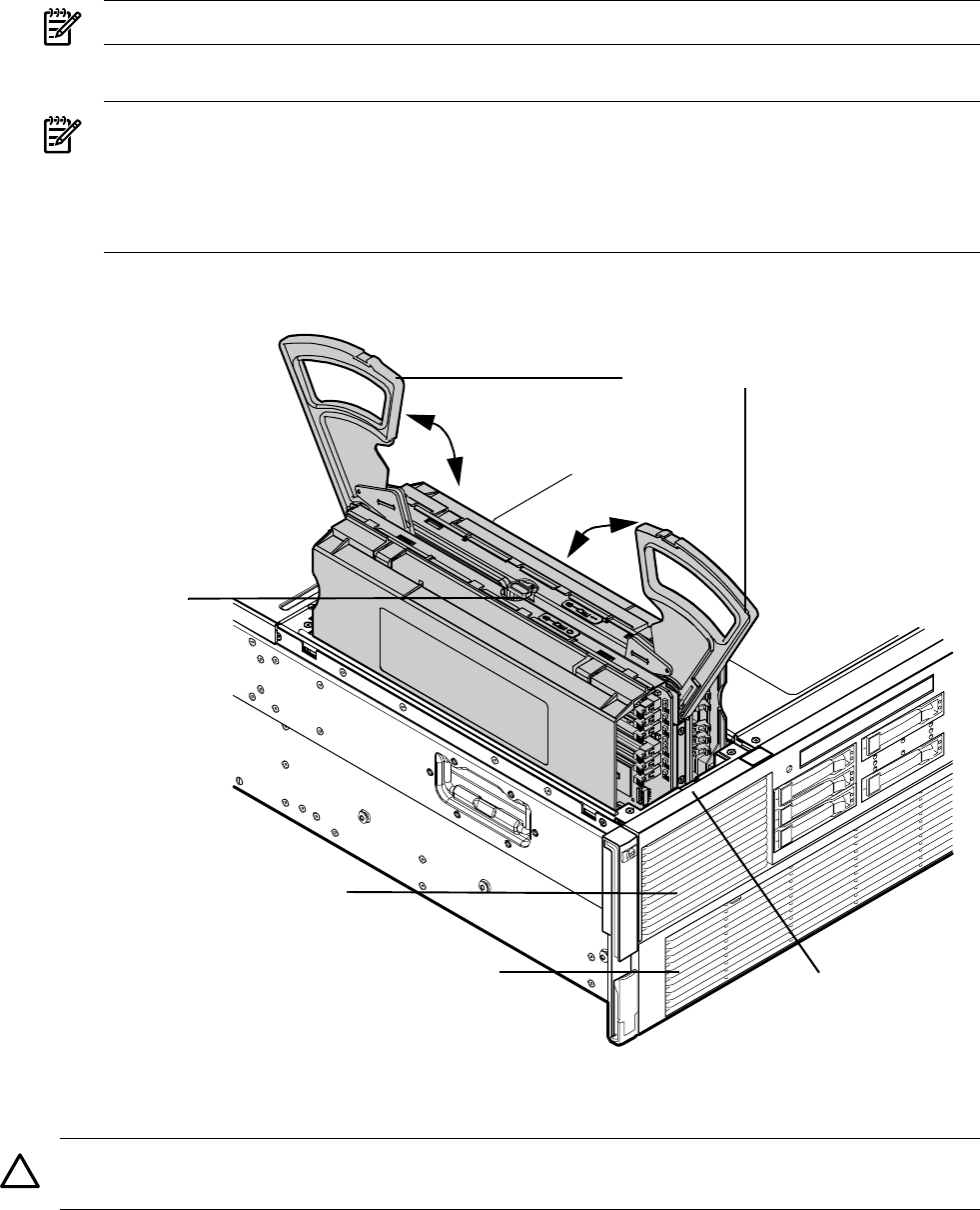
Figure 6-12 Removing and Replacing the Memory Carrier Assembly
Extraction Handle
Release Button
Extraction Handles
Front Chassis
Guide Slot
Front Bezel
Processor Board Assembly
Access Door
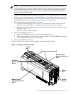
Replacing the Memory Carrier Assembly
CAUTION: Ensure the processor board assembly is fully seated before you replace the memory
carrier assembly. The processor board assembly access door must be flush with the front bezel.
To replace the memory carrier assembly, follow these steps:
1. Ensure that the extraction handles are positioned in the outward, unlocked position.
2. Align the memory carrier assembly with the front and rear chassis guide slots.
Removing and Replacing the Memory Carrier Assembly 205