


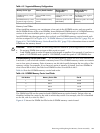
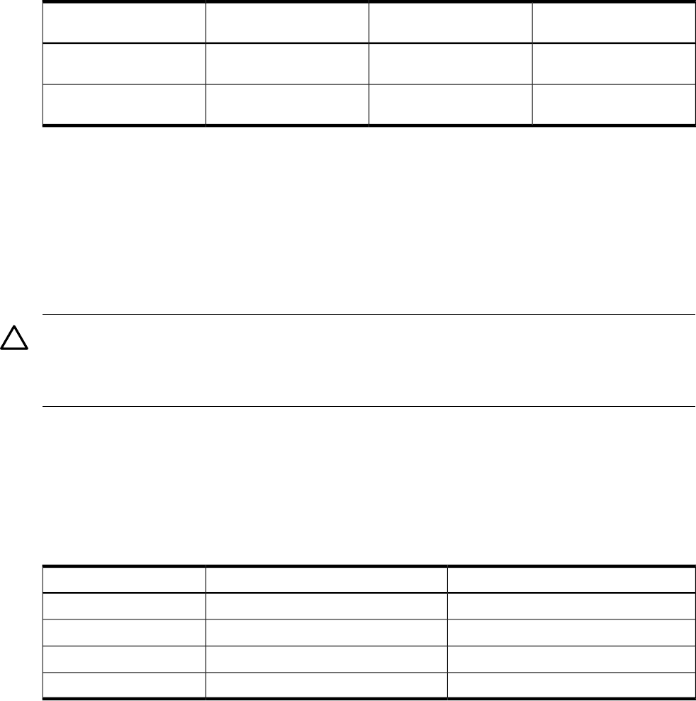
Table 6-5 Supported Memory Configurations
Maximum Memory
Configuration
Minimum Memory
Configuration
Memory Boards InstalledMemory Carrier Type
32 GB (four pairs: eight 4
GB DIMMs)
2 GB (one pair: two 1-GB
DIMMs)
Two 4-DIMM memory
boards
8-DIMM memory carrier
(standard)
96 GB (six quads: 24 X 4 GB
DIMMs)
2 GB (one quad: four 512
MB DIMMs)
Two 12-DIMM memory
boards
24-DIMM memory carrier
(optional, high-capacity)
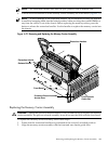
Memory Load Order
When installing memory, use a minimum of one pair in the 8-DIMM carrier, and one quad in
the 24-DIMM carrier, of like-sized DIMMs. Insert additional DIMMs into 8- or 24-DIMM memory
carriers in the next available pair or quad, in order of capacity from largest to smallest.
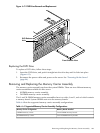
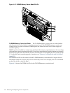
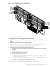
Install DIMMs into the appropriate slots on the 8- and 24-DIMM memory carrier boards; each
slot has a unique ID. Use Figure 6-15: “8-DIMM Memory Carrier Board Slot IDs” (page 210), or
Figure 6-16: “24-DIMM Memory Carrier Board Slot IDs” (page 211) to determine where to install
DIMMs on the memory board.
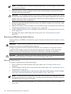
CAUTION: Failure to observe the following cautions results in system degradation or failure:
• Do not mix DIMM sizes or types within a pair or quad.
• Load DIMM quads in order of capacity from largest to smallest. For example, if you have a
quad of 2 GB DIMMs and a quad of 1 GB DIMMs, install the quad of 2 GB DIMMs first.
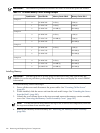
8-DIMM Memory Carrier Load Order The 8-DIMM memory carrier has two sides labeled side
0 and side 1, each of which contains a memory board. The 8-DIMM memory carrier can contain
one to four pairs of memory. Pairs of memory are divided equally between the two sides of the
memory carrier. For example, if you have two pairs of memory to install, load two DIMMs in
slots 0A and 0B of side 0, and load two DIMMs in slots 0A and 0B of side 1.
Table 6-6 lists the 8-DIMM memory carrier load order.
Table 6-6 8-DIMM Memory Carrier Load Order
Slot IDMemory Carrier SidePair Number
0A 0BSide 01
0A 0BSide 12
1A 1BSide 03
1A 1BSide 14
The DIMM slot IDS are the same for both 8-DIMM memory carrier boards. Unique slots are
identified within the carrier by the side in which they reside. For example, slot 0A is identified
as slot 0A, side 0; or slot 0A, side 1.
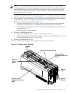
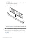
Figure 6-15 shows the DIMM slot IDs for the 8-DIMM memory carrier board.
Removing and Replacing the Memory Carrier Assembly 209