


Table B-3 Cable kit part numbers (continued)
Part NumberDescriptionType of Cable
389662-B21Multi-lane 76-cm (30-in) cableInternal SAS/SATA
391330-B21Multi-lane 48-cm (19-in) cableInternal SAS/SATA
Additional cables can be ordered from an authorized HP reseller or authorized HP service
provider. If the cable that you need is not listed here, or if you need additional ordering
information, see the HP website at http://www.hp.com.
This chapter contains the following topics:
• “Installing the HP Eight-Internal Port SAS Host Bus Adapter” (page 269)
• “Installing the HP Smart Array P600” (page 270)
• “Installing the HP Smart Array P400” (page 271)
• “Installing the HP Smart Array P800” (page 275)
Installing the HP Eight-Internal Port SAS Host Bus Adapter
On HP Integrity rx3600 and rx6600 servers, the HP Eight-Internal Port SAS Host Bus Adapter is
supported by HP-UX and OpenVMS operating systems. It should be installed in slot 1 if one
card is to be installed, and slot 2 if slot 1 is already occupied.
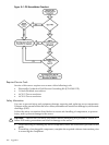
The installation procedure involves the following steps:
• Preparing the server
• Installing the adapter hardware.
• Connecting the Adapter to Other Devices
• Completing the adapter installation procedure, including updating the firmware and
installing drivers.
For more information, including configuring and troubleshooting, refer to the HP 8 Internal Port
SAS Host Bus Adapter (SAS Controller) Users Guide which can be found in the I/O Cards and
Networking Software collection under SAS Host Bus Adapters at:
http://www.docs.hp.com
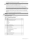
Procedure B-2 Preparing the Server
To prepare the server for add or replacement, use the following steps:
1. Perform a normal system shutdown.
2. Power down the server.
3. Power down all peripheral devices attached to the server.
4. Unplug the ac power cord from the outlet, and then unplug it from the server
5. Disconnect all peripheral devices attached to the server.
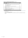
Procedure B-3 Installing the Adapter Hardware
1. Remove or open the server access panel and locate the PCI/PCI-X bus expansion slots. (For
detailed instructions, see the documentation that was provided with the server.)
2. Select the appropriate core I/O slot.
3. Open the MRL.
a. Press the indentation on the MRL to release it from the chassis wall.
b. Lift the edge of the MRL, and rotate it upward 90 degrees until it rests against the chassis
wall and the PCI/PCI-X/PCIe card bulkhead filler is fully exposed.
4. Remove the PCI/PCI-X/PCIe bulkhead filler. Save it to use for if you later decide to remove
the adapter and leave the slot empty.
5. Insert the adapter into the slot, and press it firmly into place. The contacts on the adapter
edge should be fully seated in the system board connector.
Installing Core I/O Cards 269