


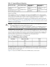
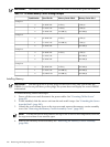
IMPORTANT: The number in parenthesis indicates the order in which the quads are loaded.
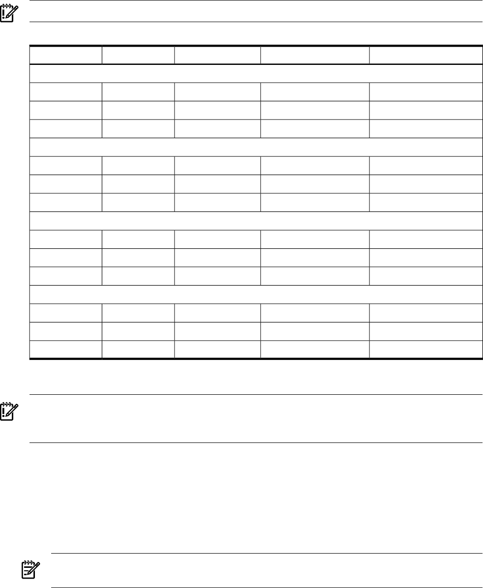
Table 6-7 24-DIMM Memory Carrier Loading Examples
Memory Carrier Side 1Memory Carrier Side 0Quad Slot IDsQuad Number
Example 1
2 GB (2)2 GB (1)0A 0B 0C 0D0
1 GB (4)1 GB (3)1A 1B 1C 1D1
512 MB (6)512 MB (5)2A 2B 2C 2D2
Example 2
1 GB (2)2 GB (1)0A 0B 0C 0D0
1 GB (3)512 MB (4)1A 1B 1C 1D1
512 MB (5)2A 2B 2C 2D2
Example 3
1 GB (2)2 GB (1)0A 0B 0C 0D0
512 MB (3)1A 1B 1C 1D1
512 MB (4)2A 2B 2C 2D2
Example 4
512 MB (2)2 GB (1)0A 0B 0C 0D0
512 MB (3)512 MB (5)1A 1B 1C 1D1
512 MB (4)512 MB (6)2A; 2B 2C 2D2
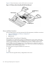
Installing Memory
IMPORTANT: You must pull the ac power plugs on the server every time you modify the
DIMMs. If you do not pull the ac power plugs, the system does not display the correct DIMM
information.
To install memory, follow these steps:
1. Power off the server and disconnect the power cables. See “Powering Off the Server”
(page 95).
2. If rack installed, slide the server out from the rack until it stops. See “Extending the Server
from the Rack” (page 180).
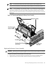
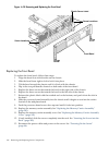
3. Unlatch the cover release lever on the top cover and remove the memory carrier assembly
cover. See “Removing the Memory Carrier Assembly Cover” (page 183).
NOTE: You do not need to fully remove the top cover to service this component; however,
the top cover release lever must be open.
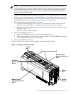
4. Remove the memory carrier assembly. See “Removing the Memory Carrier Assembly”
(page 204).
212 Removing and Replacing Server Components