


• Thin cables and small connectors (assists with cooling and ease cable management issues)
• Increased scalability (expanders enable support for thousands of SAS devices)
The SAS backplane board attaches to an interconnect board that functions as a link between the
midplane board and the SAS backplane board.
WARNING! Ensure that the system is powered off and all power sources have been disconnected
from the server prior to performing this procedure.
Voltages are present at various locations within the server whenever an ac power source is
connected. This voltage is present even when the main power switch is in the off position.
Failure to observe this warning can result in personal injury or damage to equipment.
CAUTION: Observe all ESD safety precautions before attempting this procedure. Failure to
follow ESD safety precautions can result in damage to the server.
Removing the SAS Backplane Board
To remove the SAS backplane board, follow these steps:
1. Power off the server and disconnect the power cables. See “Powering Off the Server”
(page 95).
2. If rack installed, slide the server completely out from the rack. See “Extending the Server
from the Rack” (page 180).
3. Remove the top cover. See “Removing the Top Cover” (page 181).
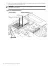
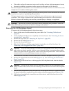
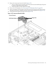
4. Remove the air baffle (Figure 6-33).
5. Remove the clear plastic cover.
6. Slide the SAS drives and fillers approximately two inches out of the drive bays. See
“Removing a Hot-Pluggable Disk Drive” (page 188).
CAUTION: When disconnecting the SAS cables, note the labeling on the cables. Both cables
and sockets are clearly marked with the correct channel. When reconnecting these cables,
match each cable with the appropriate socket on the SAS backplane board. If the cables are
mismatched, the server operating system may not reboot.
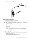
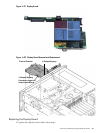
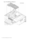
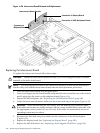
7. Disconnect the SAS cables from the connectors on the SAS backplane board (Figure 6-34).
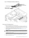
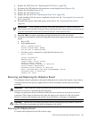
8. Remove the interconnect board air baffle (Figure 6-35). See “Removing the Interconnect
Board” (page 250).
9. Push down on the release lever to disengage the SAS backplane board from the chassis
(Figure 6-34).
CAUTION: Do not use the release lever as a handle to remove the SAS backplane board.
Failure to observe this caution can result in damage to the release lever and the SAS backplane
board.
10. Use the sheet metal bracket that surrounds the SAS backplane board as a handle and slide
the board to the left to unplug it from the socket on the interconnect board (Figure 6-34).
11. Pull the board straight back toward the rear of the chassis, and lift the board out of the
chassis (Figure 6-34).
Removing and Replacing the SAS Backplane Board 247