


NOTE: To avoid damage to the memory carrier extraction handles, HP recommends
rotating the handles inward and snapping them into the locked position when servicing the
system DIMMs or any time the carrier is out of the chassis. Before replacing the memory
carrier, press the button to release the extraction handles. Use the handles to replace the
memory carrier into the chassis.
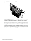
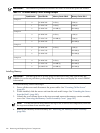
5. To locate the DIMM you need to remove, use Figure 6-15: “8-DIMM Memory Carrier Board
Slot IDs” (page 210), or Figure 6-16: “24-DIMM Memory Carrier Board Slot IDs” (page 211).
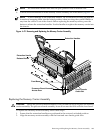
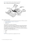
6. Lay the memory carrier assembly on side 0 or side 1 so that the memory board containing
the DIMMs that require servicing faces upward (Figure 6-13 (page 207)).
7. Remove the memory carrier assembly side cover.
a. Press the release tabs (Figure 6-13 (page 207)) on both sides of the extraction handle
release button until the side cover releases from the top center of the assembly.
b. Rotate the side cover slightly to free the tabs from the retaining slots at the base of the
assembly (Figure 3-8).
c. Lift the side cover off the assembly.
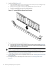
8. Release the DIMM from the slot.
a. Identify the DIMM you want to remove on the memory board.
b. Push the appropriate extraction levers found on either side of the DIMM slot outward
to the open position (Figure 6-17 (page 214)).
9. Remove the DIMM from the slot.
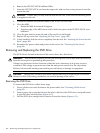
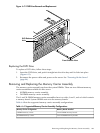
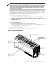
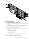
Figure 6-13 shows the memory carrier assembly removed from the chassis.
Figure 6-13 Memory Carrier Assembly
Memory
Boards
Extraction
Handles release
Button
Extraction Handles (Closed)
Memory Carrier
Assembly Side cover;
Memory Carrier
Assembly Side Cover;
Release
tabs
Release
Tabs
Side 1
Side 0
Removing and Replacing the Memory Carrier Assembly 207