


The server can contain one or two dual-core processors that provide the following configuration
options:
• 1P/2C (One processor/two cores)
• 2P/4C (Two processors/four cores)
WARNING! Ensure that the system is powered off and all power sources have been disconnected
from the server prior to performing this procedure.
Voltages are present at various locations within the server whenever an ac power source is
connected. This voltage is present even when the main power switch is in the off position.
Failure to observe this warning can result in personal injury or damage to equipment.
CAUTION: Intel Montvale processors cannot be intermixed with similar Montecito processors.
Processor speed and cache size must be identical for all processors in a system. Whether
upgrading, replacing or adding an additional processor, to ensure compatibility use processors
with identical part numbers.
Failure to observe this caution results in performance degradation or system failure.
CAUTION: Observe all ESD safety precautions before attempting this procedure. Failure to
follow ESD safety precautions can result in damage to the server.
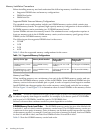
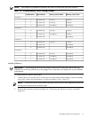
Processor Load Order
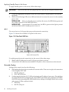
The server can have up to two dual-core processors on the processor board. The slots on the
processor board are labeled Module 0 and Module 1.
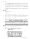
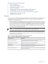
Table 3-7 lists the processor load sequence.
Table 3-7 Processor Load Order
SlotDual-Core Processor
Module 01
Module 12
Required Tools
To install processors, use the processor install tool fastened to the processor board.
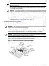
Installing a Dual-Core Processor
To install a dual-core processor, follow these steps:
1. Remove the memory carrier assembly cover. See “Removing the Memory Carrier Assembly
Cover” (page 57).
NOTE: You do not need to fully remove the top cover to service this component; however,
the top cover release lever must be open.
2. Remove the memory carrier assembly. See “Removing the Memory Carrier Assembly”
(page 65)
NOTE: You must remove the memory carrier because it attaches directly to the processor
board.
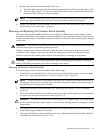
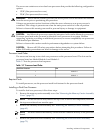
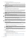
3. Remove the processor board assembly. See “Removing the Processor Board Assembly”
(page 73).
Installing Additional Components 75