


3. Power down the server.
CAUTION: In systems that use external data storage, be sure that the server is the first unit
to be powered down and the last to be powered back up. Taking this precaution ensures
that the system does not erroneously mark the drives as failed when the server is powered
up.
4. Power down all peripheral devices that are attached to the server.
5. Unplug the ac power cord from the outlet and then from the server.
6. Disconnect all peripheral devices from the server.
Procedure B-25 Installing the controller board
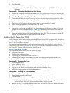
1. Remove or open the access panel.
2. Select the appropriate PCI Express slot (3 or 4).
3. Open the MRL.
a. Press the indentation on the MRL to release it from the chassis wall.
b. Lift the edge of the MRL, and rotate it upward 90 degrees until it rests against the chassis
wall and the PCI/PCI-X/PCIe card bulkhead filler is fully exposed.
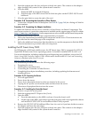
4. Remove the PCI/PCI-X/PCIe bulkhead filler. Save it to use for if you later decide to remove
the adapter and leave the slot empty.
5. Insert the adapter into the slot, and press it firmly into place. The contacts on the adapter
edge should be fully seated in the system board connector.
6. Close the MRL.
a. Rotate the MRL downward 90 degrees.
b. Push the edge of the MRL down until it clicks into place on the PCI/PCI-X/PCIe card
bulkhead.
7. Close the gate latch to secure the end of the card.
Connecting the Controller to Other Devices
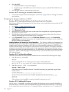
Procedure B-26 Connecting to Internal Storage
• Connect the Adapter to the SAS backplane. See Table B-3 (page 268) for a listing of Cable kit
part numbers.
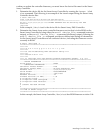
Procedure B-27 Connecting to External Storage
1. Connect an external SAS cable to the external port of the controller.
a. Pull back the tab on the mini SAS 4x connector on the cable
b. Insert the cable connector into the external port of the controller.
c. Release the tab.
2. Connect the other end of the cable to the SAS input connector of the external storage
enclosure.
• If the enclosure uses a standard SAS 4x connector, insert the cable connector into the
enclosure connector, and then tighten the lock screws on the cable connector.
• If the enclosure uses a mini SAS 4x connector, pull back the tab on the cable connector,
insert the cable connector into the enclosure connector, and then release the tab.
Table B-5 SAS cable part numbers
Option kit part numberType of cableApproximate cable length
419570-B21Mini SAS 4x to standard SAS 4x1 m (3 ft.)
407339-B21Mini SAS 4x to mini SAS 4x2 m (6 ft.)
419571-B21Mini SAS 4x to standard SAS 4x
432238-B21Mini SAS 4x to mini SAS 4x4 m (13 ft.)
419572-B21Mini SAS 4x to standard SAS 4x
278 Upgrades