


Protocols — Device Path Protocol
Version 1.10 12/01/02 8-15
#define EFI_PC_ANSI_GUID \
{ 0xe0c14753,0xf9be,0x11d2,0x9a,0x0c,0x00,0x90,0x27,0x3f,0xc1,0x4d }
#define EFI_VT_100_GUID \
{ 0xdfa66065,0xb419,0x11d3,0x9a,0x2d,0x00,0x90,0x27,0x3f,0xc1,0x4d }
#define EFI_VT_100_PLUS_GUID \
{ 0x7baec70b,0x57e0,0x4c76,0x8e,0x87,0x2f,0x9e,0x28,0x08,0x83,0x43 }
#define EFI_VT_UTF8_GUID \
{ 0xad15a0d6,0x8bec,0x4acf,0xa0,0x73,0xd0,0x1d,0xe7,0x7e,0x2d,0x88 }
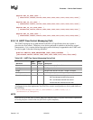
8.3.4.14 UART Flow Control Messaging Path
The UART messaging device path defined in the EFI 1.02 specification does not contain a
provision for flow control. Therefore, a new device path node is needed to declare flow control
characteristics. It is a vendor-defined messaging node which may be appended to the UART node
in a device path. It has the following definition:
#define DEVICE_PATH_MESSAGING_UART_FLOW_CONTROL \
{0X37499A9D,0X542F,0X4C89,0XA0,0X26,0X35,0XDA,0X14,0X20,0X94,0XE4}
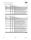
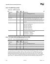
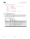
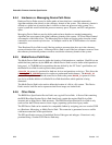
Table 8-23. UART Flow Control Messaging Device Path
Mnemonic
Byte
Offset
Byte
Length
Description
Type 0 1 Type 3 – Messaging Device Path
Sub-Type 1 1 Sub-Type 10 – Vendor
Length 2 2 Length of this structure in bytes. Length is 24 bytes.
Vendor_GUID 4 16
DEVICE_PATH_MESSAGING_UART_FLOW_CONTROL
Flow_Control_Map 20 4 Bitmap of supported flow control types.
Bit 0 set indicates hardware flow control.
Bit 1 set indicates Xon/Xoff flow control.
All other bits are reserved and are clear.
A debugport driver that implements Xon/Xoff flow control would produce a device path similar to
the following:
ACPI(PciRootBridge)/Pci(0x1f,0)/ACPI(PNP0501,0)/UART(115200,n,8,1)
/UartFlowCtrl(2)/DebugPort()
NOTE
If no bits are set in the Flow_Control_Map, this indicates there is no flow control and is equivalent
to leaving the flow control node out of the device path completely.