Extensible Firmware Interface Specification
E-12 12/01/02 Version 1.10
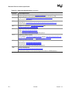
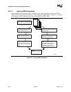
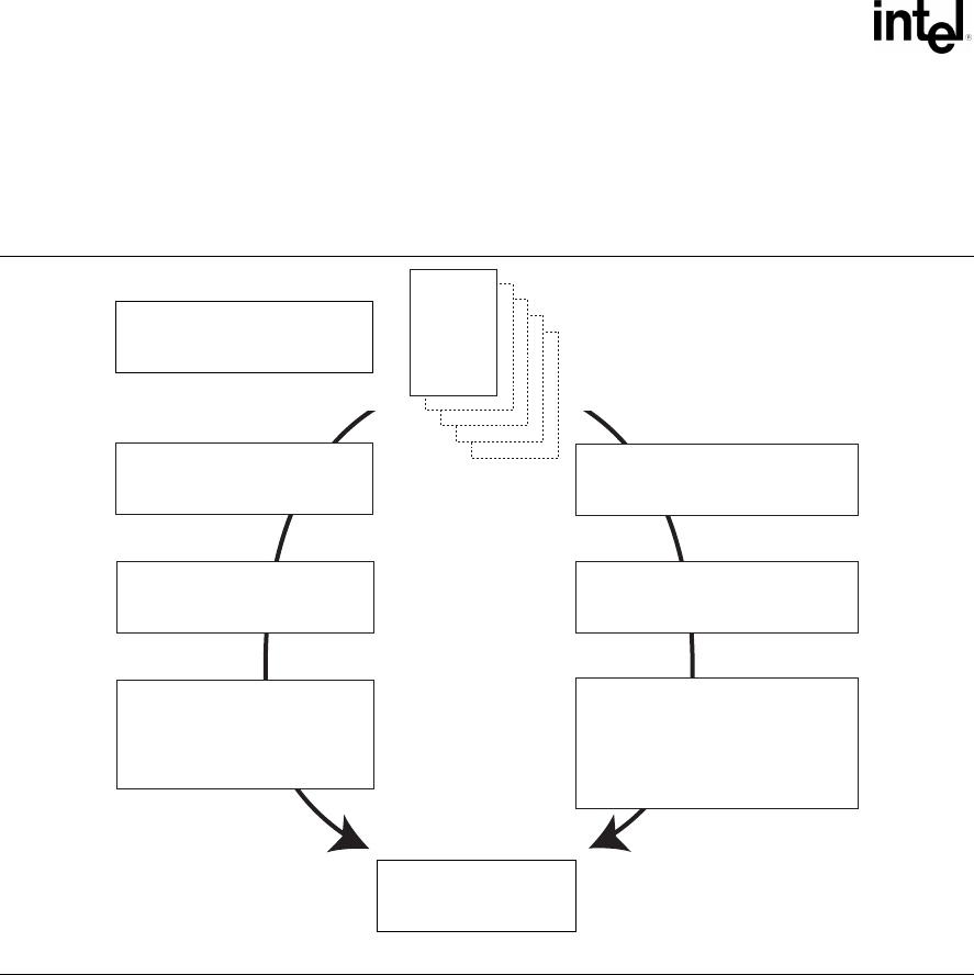
E.2.1.1 Issuing UNDI Commands
How commands are written and status is checked varies a little depending on the type of UNDI
(H/W or S/W) implementation being used. The command flowchart shown in Figure E-3 is a high-
level diagram on how commands are written to both H/W and S/W UNDI.
OM13184
Step 1
Fill in CDB(s). Commands may
be linked if supported by UNDI.
Step 2 (H/W UNDI)
Write physical address of first
CDB to CDBaddr register.
Step 3 (H/W UNDI)
Initiate command execution
(write to UNDI Command port)
Step 4 (H/W UNDI)
Wait for completion status. Can
be polled in separate thread of
interrupt driven, if supported by
UNDI.
Step 2 (S/W UNDI)
Push virtual address of first CDB
onto CPU stack.
Step 3 (S/W UNDI)
Initiate command execution (Call
S/W UNDI API entry point).
Step 4 (S/W UNDI)
Wait for completion status. Some
S/W UNDI implementations can
be polled or interrupt driven,
others will not return until
command execution completes.
CDB
Step 5
Issue more commands.
Figure E-3. Issuing UNDI Commands


