


32/64-Bit UNDI Specification
Version 1.10 12/01/02 E-7
E.2 Overview
There are three major design changes between this specification and the 16-bit UNDI in version 2.1
of the PXE Specification:
• A new architectural hardware interface has been added.
• All UNDI commands use the same command format.
• BC is no longer part of the UNDI ROM.
E.2.1 32/64-bit UNDI Interface
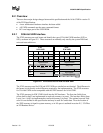
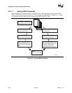
The !PXE structures are used locate and identify the type of 32/64-bit UNDI interface (H/W or
S/W), as shown in Figure E-2. These structures are normally only used by the system BIOS and
universal network drivers.
OM13183
!PXE
H/W UNDI
Offset
0x00
0x04
0x08
0x0C
0x00
0x01 0x02 0x03
Signature
Len Fudge Rev IFcnt
Major Minor reserved
Implementation
Status
Command
CDBaddr
Len
Len +
0x04
Len +
0x08
Len +
0x0C
!PXE
S/W UNDI
Offset
0x00
0x04
0x08
0x0C
0x00
0x01 0x02
0x03
Signature
Len Fudge Rev IFcnt
Major Minor reserved
Implementation
Entry Point
reserved #bus
BusTypes(s)
0x10
0x14
0x18
0x1C
0x10
reserved
0x20
More BusTypes(s)
Figure E-2. !PXE Structures for H/W and S/W UNDI
The !PXE structures used for H/W and S/W UNDIs are similar but not identical. The difference in
the format is tied directly to the differences required by the implementation. The !PXE structures
for 32/64-bit UNDI are not compatible with the !PXE structure for 16-bit UNDI.
The !PXE structure for H/W UNDI is built into the NIC hardware. The first nine fields (from
offsets 0x00 to 0x0F) are implemented as read-only memory (or ports). The last three fields (from
Len to Len + 0x0F) are implemented as read/write memory (or ports). The optional reserved field
at 0x10 is not defined in this specification and may be used for vendor data. How the location of
the !PXE structure is found in system memory, or in I/O space is outlined in section E.5, “UNDI as
an EFI Runtime Driver.”