


Protocols — Console Support
Version 1.10 12/01/02 10-25
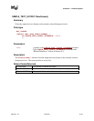
10.4.2 UGA Draw Protocol
The EFI_UGA_DRAW_PROTOCOL supports three member functions to support the limited
graphics needs of the pre-OS space. These member functions allow the caller to draw to a
virtualized frame buffer, to get the current video mode, and to set a video mode. These simple
primitives are sufficient to support the general needs of pre-OS firmware code
10.4.3 Blt Buffer
The basic graphics operation in the EFI_UGA_DRAW_PROTOCOL is the Block Transfer or Blt.
The Blt operation allows data to be read or written to the video adapter’s video memory. The Blt
operation abstracts the video adapters hardware implementation by introducing the concept of a
software Blt buffer.
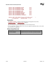
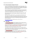
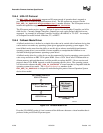
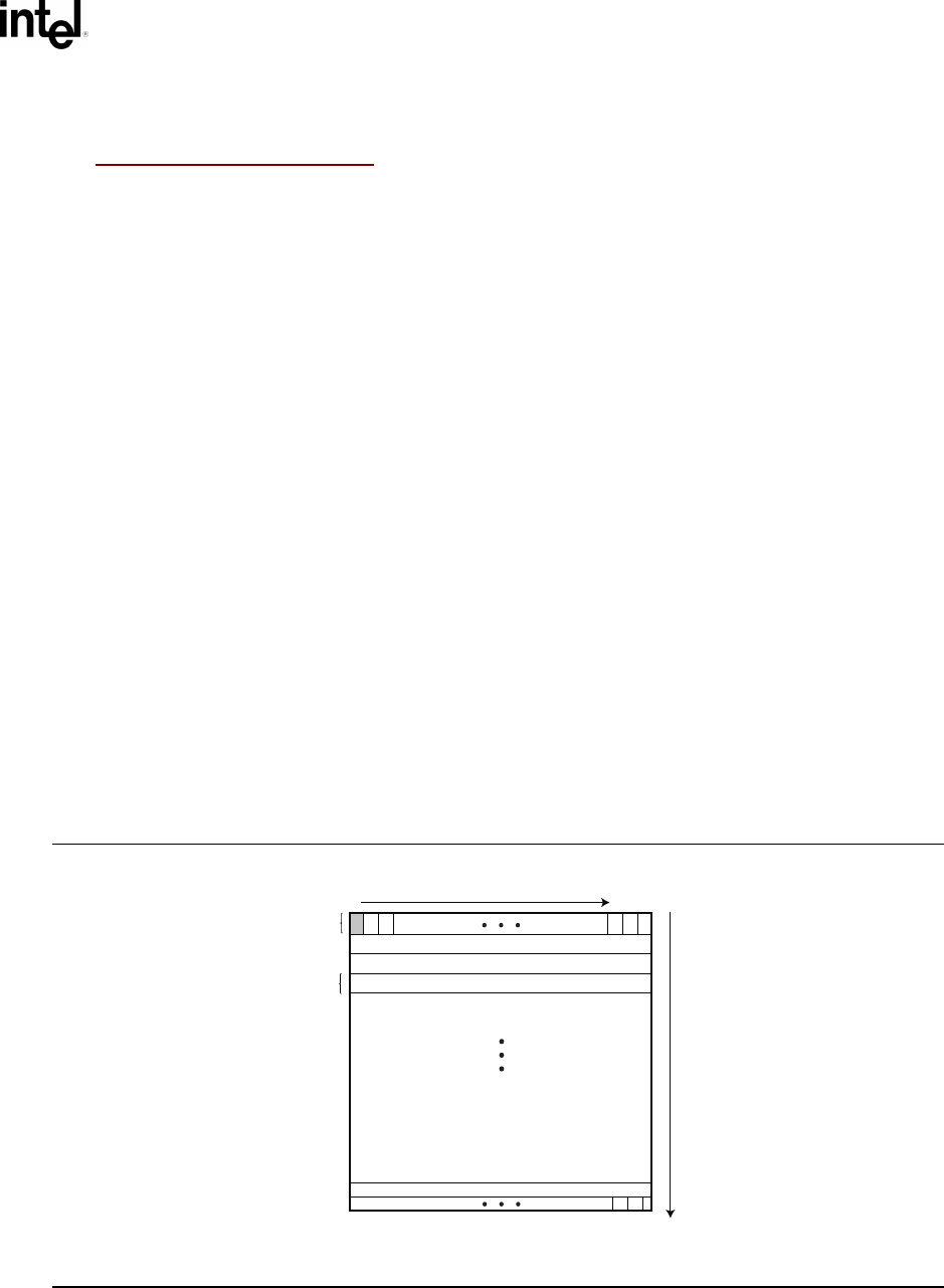
The frame buffer abstracts the video display as an array of pixels. Each pixels location on the video
display is defined by its X and Y coordinates. The X coordinate represents a scan line. A scan line
is a horizontal line of pixels on the display. The Y coordinate represents a vertical line on the
display. The upper left hand corner of the video display is defined as (0, 0) where the notation
(X, Y) represents the X and Y coordinate of the pixel. The lower right corner of the video display
is represented by (Width –1, Height -1).
The software Blt buffer is structured as an array of pixels. Pixel (0, 0) is the first element of the
software Blt buffer. The Blt buffer can be thought of as a set of scan lines. It is possible to convert
a pixel location on the video display to the Blt buffer using the following algorithm: Blt buffer
array index = Y * Width + X.
Each software Blt buffer entry represents a pixel that is comprised of a 32-bit quantity. Byte zero
of the Blt buffer entry represents the Red component of the pixel. Byte one of the Blt buffer entry
represents the Green component of the pixel. Byte two of the Blt buffer entry represents the Blue
component of the pixel. Byte three of the Blt buffer entry is reserved and must be zero.
OM13157
Software BLT Buffer
(0, 0)
X-axis
(Width -1, 0)
Y-axis
Pixel
Scan Line
(0, Height - 1)
(Width -1, Height - 1)
Figure 10-1. Software BLT Buffer