


Extensible Firmware Interface Specification
C-2 12/01/02 Version 1.10
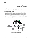
The remainder of this appendix describes how to construct a device path for three example devices
from the system in Figure C-1. The following is a list of the examples used:
• Legacy floppy
• IDE Disk
• Secondary root PCI bus with PCI to PCI bridge
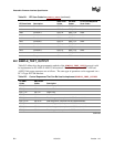
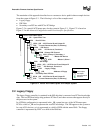
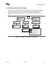
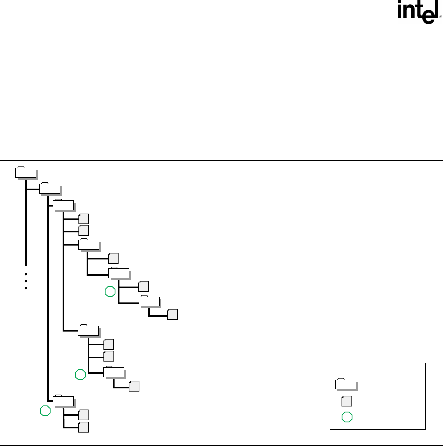
Figure C-2 is a partial ACPI name space for the system in Figure C-1. Figure C-2 is based on
Figure 5-3 in the Advanced Configuration and Power Interface Specification.
OM13180
Root of ACPI Name Space
\_ SB - System Bus Tree
PCI0 - Root PCI Bus
_HID & _UID - ACPI Device ID and Unique ID
_CRS - Current Resources (Bus, I/O, Memory)
IDE0 - IDE Device
_ADR - PCI Device #, Function #
PRIM - Primary IDE Channel
_ADR - Primary 0, Secondary 1
MAST - Master IDE Device
2
_ADR - Master 0, Slave 1
ISA0 - ISA Bridge
_HID & _UID - ACPI Device ID and Unique ID
_ADR - PCI Device #, Function #
FLPY - Legacy Floppy
_HID - Address of Floppy
PCI0 - Secondary Root PCI Bus
_HID & _UID - ACPI Device ID and Unique ID
_CRS - Current Resources (Bus, I/O, Memory)
1
3
KEY...
Device Object
Data Object
Example Platform
Reference
1
Figure C-2. Partial ACPI Name Space for Example System
C.2 Legacy Floppy
The legacy floppy controller is contained in the SIO chip that is connected root PCI bus host bridge
chip. The root PCI host bridge chip produces PCI bus 0, and other resources that appear directly to
the processors in the system.
In ACPI this configuration is represented in the _SB, system bus tree, of the ACPI name space.
PCI0 is a child of _SB and it represents the root PCI host bridge. The SIO appears to the system to
be a set of ISA devices, so it is represented as a child of PCI0 with the name ISA0. The floppy
controller is represented by FLPY as a child of the ISA0 bus.