Version 1.10 12/01/02 C-1
Appendix C
Device Path Examples
This appendix presents an example EFI Device Path and explains its relationship to the ACPI name
space. An example system design is presented along with its corresponding ACPI name space.
These physical examples are mapped back to EFI Device Paths.
C.1 Example Computer System
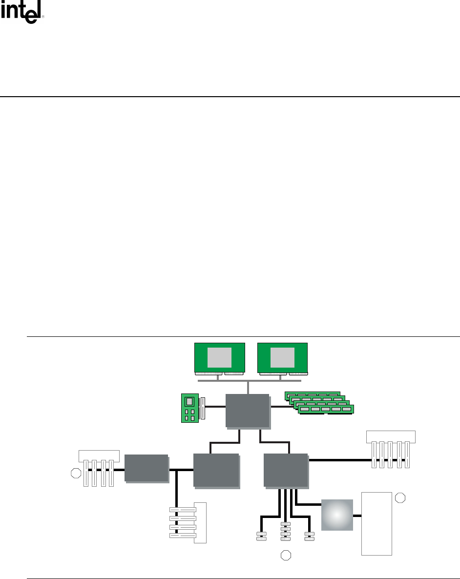
Figure C-1 represents a hypothetical computer system architecture that will be used to discuss the
construction of EFI Device Paths. The system consists of a memory controller that connects
directly to the processors’ front side bus. The memory controller is only part of a larger chipset,
and it connects to a root PCI host bridge chip, and a secondary root PCI host bridge chip. The
secondary PCI host bridge chip produces a PCI bus that contains a PCI to PCI bridge. The root PCI
host bridge produces a PCI bus, and also contains USB, ATA66, and AC ’97 controllers. The root
PCI host bridge also contains an LPC bus that is used to connect a SIO (Super IO) device. The SIO
contains a PC-AT-compatible floppy disk controller, and other PC-AT-compatible devices like a
keyboard controller.
OM13179
CPU
CPU
AGP
PDRAM
PCI 33MHz
LPC
PCI Slots
3
PCI Slots
PCI Slots
2
1
FDC
KBD
GPIO
Serial
Parallel
Mouse
IR
SIO
USB ATA66 AC'97
Memory
Controller
Secondary
PCI Host
Bridge
Root PCI
Host
Bridge
Memory
Controller
PCI to PCI
Bridge
Figure C-1. Example Computer System


