


Intel
®
IXF1104 4-Port Gigabit Ethernet Media Access Controller
Datasheet 100
Document Number: 278757
Revision Number: 009
Revision Date: 27-Oct-2005
5.5.1 MDIO Address
The 5-bit PHY address for the MDIO transactions can be set in the “MDIO Single Command
($0x680)". Bits 5:2 of the PHY address are fixed to a value of 0. Bits 1 and 0 are programmable in
bits 9 and 8 of “MDIO Single Command ($0x680)".
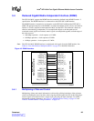
5.5.2 MDIO Register Descriptions
For complete information on the MDI registers, refer to the Table 142 “MDIO Single Command
($0x680)” on page 211, Table 143 “MDIO Single Read and Write Data ($0x681)” on page 211,
Table 144 “Autoscan PHY Address Enable ($0x682)” on page 212, and Table 145 “MDIO Control
($0x683)” on page 212.
5.5.3 Clear When Done
The MDI Command register bit, in the “MDIO Single Command ($0x680)", clears upon command
completion and is set by the user to start the requested single MDIO Read or Write operation. This
bit is cleared automatically upon operation completion.
5.5.4 MDC Generation
The MDC clock is used for the MDIO/MDC interface. The frequency of the MDC clock is
selectable by setting bit 0, MDC Speed, in an IXF1104 MAC configuration register (see Table 145
“MDIO Control ($0x683)” on page 212).
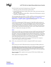
5.5.4.1 MDC High-Frequency Operation
The high-frequency MDC is 18 MHz, derived from the 125-MHz system clock by dividing the
frequency by 7.
The duty cycle is as follows:
• MDC High duration: 3 x (1/125 MHz) = 3 x 8 ns = 24 ns
• MDC Low duration: 4 x (1/125 MHz) = 4 x 8 ns = 32 ns
• MDC runs continuously after reset
Refer to Figure 41 “MDC High-Speed Operation Timing” on page 145 for the high-frequency
MDC timing diagram.
5.5.4.2 MDC Low-Frequency Operation
The low-frequency MDC is 2.5 MHz, which is derived from the 125-MHz system clock by
dividing the frequency by 50.
The duty cycle is as follows:
• MDC High duration: 25 x (1/125 MHz) = 25 x 8 ns = 200 ns
• MDC Low duration: 25 x (1/125 MHz) = 25 x 8 ns = 200 ns
• MDC runs continuously after reset