


Intel
®
IXF1104 4-Port Gigabit Ethernet Media Access Controller
Datasheet 156
Document Number: 278757
Revision Number: 009
Revision Date: 27-Oct-2005
8.3 Per Port Registers
Section 8.4 covers all of the registers that are replicated in each port of the IXF1104 MAC. These
registers perform an identical function in each port.
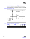
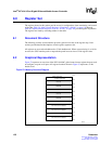
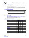
The address vector for the IXF1104 MAC is 11 bits wide. This allows for 7 bits of port-specific
access and a 4-bit vector to address each port and all global registers. The address format is shown
in Figure 54.
8.4 Register Map
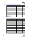
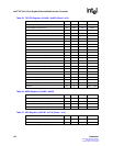
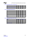
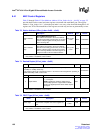
Table 59 through Table 69 “Optical Module Registers ($ 0x799 - 0x79F)” on page 162 present the
IXF1104 MAC memory map details. Global control and status registers are used to configure or
report on all ports, and some registers are replicated on a per-port basis.
Note: All IXF1104 MAC registers are 32 bits.
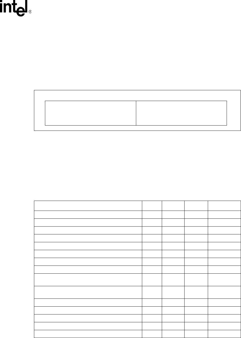
Figure 54. Register Overview Diagram
Port Select & Global Registers Per-Port Registers
10
0
6
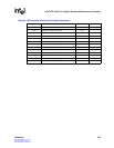
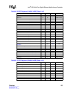
Table 59. MAC Control Registers ($ Port Index + Offset) (Sheet 1 of 2)
Register Bit Size Mode
1
Ref Page Offset
“Station Address ($ Port_Index +0x00 – +0x01)” Low 32 R/W 163 0x00
“Station Address ($ Port_Index +0x00 – +0x01)” High 32 R/W 163 0x01
“Desired Duplex ($ Port_Index + 0x02)” 32 R/W 163 0x02
“FD FC Type ($ Port_Index + 0x03)” 32 R/W 163 0x03
Reserved 32 R – 0x04
“Collision Distance ($ Port_Index + 0x05)” 32 R/W 164 0x05
“Collision Threshold ($ Port_Index + 0x06)” 32 R/W 164 0x06
“FC TX Timer Value ($ Port_Index + 0x07)” 32 R/W 164 0x07
“FD FC Address ($ Port_Index + 0x08 – + 0x09)”
FDFCAddressLow
32 R/W 164 0x08
“FD FC Address ($ Port_Index + 0x08 – + 0x09)”
FDFCAddressHigh
32 R/W 164 0x09
“IPG Receive Time 1 ($ Port_Index + 0x0A)” 32 R/W 165 0x0A
“IPG Receive Time 2 ($ Port_Index + 0x0B)” 32 R/W 165 0x0B
“IPG Transmit Time ($ Port_Index + 0x0C)” 32 R/W 165 0x0C
Reserved – RO – 0x0D
“Pause Threshold ($ Port_Index + 0x0E)” 32 R/W 166 0x0E