


Intel
®
IXF1104 4-Port Gigabit Ethernet Media Access Controller
Datasheet 118
Document Number: 278757
Revision Number: 009
Revision Date: 27-Oct-2005
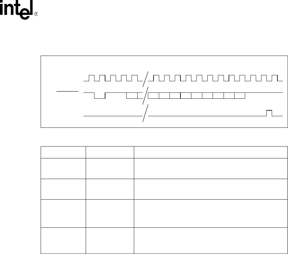
Note: The LED_DATA signal is now inverted from the state in Mode 0.
5.8.5 Power-On, Reset, Initialization
The LED interface is disabled at power-on or reset. The system software controller must enable the
LED interface. The internal state machines and output signals are held in reset until the full Intel
®
IXF1104 4-Port Gigabit Ethernet Media Access Controller device configuration is completed. This
is done by setting the LED_ENABLE bit to a logic 1 (see Table 109 “LED Control ($0x509)” on
page 190). The power-on default for this bit is logic 0.
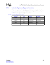
5.8.6 LED DATA Decodes
The data transmitted on the LED_DATA line is determined by programming the global operation
mode as either fiber or copper. Table 34 shows the data decode of the data for both fiber and copper
MACs.
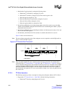
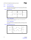
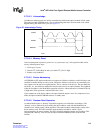
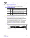
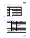
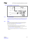
Figure 30. Mode 1 Timing
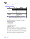
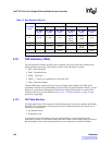
Table 33. Mode 1 Clock Cycle to Data Bit Relationship
LED_CLK Cycle LED_DATA Name LED_DATA Description
1START BIT
This bit has no meaning in Mode 1 operation and is shifted out of
the 16-stage shift register chain before the LED_LATCH signal is
asserted.
2:3 PAD BITS
These bits have no meaning in Mode 1 operation and are shifted
out of the 16-stage shift register chain before the LED_LATCH
signal is asserted.
4:15 LED DATA 1-12
These bits are the actual data to be transmitted to the 16-stage shift
register chain. The decode for each bit in each mode is defined in
Table 34 on page 119.
The data is INVERTD. Logic 1 (LED ON) = Low.
36:38 PAD BITS
These bits have no meaning in Mode 1 operation and are latched
into positions 31 and 32 in the shift register chain. These bits are
not considered as valid data and should be ignored. They should
always be a Logic 0 = High.
1 22 23 24 25 26 27 28 29 30
13534333231302928272625234
LED_CLK
LED_DATA
LED_LATCH