


Intel
®
IXF1104 4-Port Gigabit Ethernet Media Access Controller
73 Datasheet
Document Number: 278757
Revision Number: 009
Revision Date: 27-Oct-2005
5.1.2.1.3 Response to Received PAUSE Command Frames
When Flow Control is enabled in the receive direction (bit 0 in the “FC Enable ($ Port_Index +
0x12)"), the IXF1104 responds to PAUSE Command frames received from the link partner as
follows:
1. The IXF1104 checks the entire frame to verify that it is a valid PAUSE control frame
addressed to the Multicast Address 01-80-C2-00-00-01 (as specified in IEEE 802.3, Annex
31B) or has a Destinations Address matching the address programmed in the “Station Address
($ Port_Index +0x00 – +0x01)".
2. If the PAUSE frame is valid, the transmit side of the IXF1104 pauses for the required number
of PAUSE Quanta, as specified in IEEE 802.3, Clause 31.
3. PAUSE does not begin until completion of the frame currently being transmitted.
The IXF1104 response to valid received PAUSE frames is independent of the PAUSE frame filter
settings. Refer to Section 5.1.1.3.5, “Filter Pause Packets” on page 68 for additional details.
Note: Pause packets are not filtered if flow control is disabled in bit 0 of the “FC Enable ($ Port_Index +
0x12)”.
5.1.2.1.4 Half-Duplex Operation
Transmit flow control is implemented only in half-duplex operation. Upon entering the flow
control state, the MAC generates a collision for all subsequent receive packets until exiting the
flow control state. Any receive packet in progress when the MAC enters the flow control state will
not be collided with but could be lost due if there is insufficient FIFO depth to complete packet
reception. Bit 2 of the “FC Enable ($ Port_Index + 0x12)" enables the transmit flow control
function.
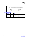
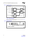
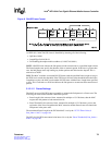
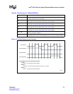
5.1.2.1.5 Transmit Pause Control Interface
The Transmit Pause Control interface allows an external device to trigger the generation of pause
frames. The Transmit Pause Control interface is completely asynchronous. It consists of three
address signals (TXPAUSEADD[2:0]) and a strobe signal (TXPAUSEFR). The required address
for this interface operation is placed on the TXPAUSEADD[2:0] signals and the TXPAUSEFR is
pulsed High and returned Low. Refer to Figure 10 “Transmit Pause Control Interface” on page 74
and Table 55 “Transmit Pause Control Interface Timing Parameters” on page 151. Table 23 shows
the valid decodes for the TXPAUSEADD[2:0] signals. Figure 10 illustrates the transmit pause
control interface.
Note: Flow control must be enabled in the “FC Enable ($ Port_Index + 0x12)” for Transmit Pause
Control interface operation.
Note: There are two additional decodes provided that allow the user to generate either an XOFF frame or
XON frame from all ports simultaneously.
The default pause quanta for each port is held by the “FC TX Timer Value ($ Port_Index + 0x07)").
The default value of this register is 0x05E after reset is applied.