


Intel
®
IXF1104 4-Port Gigabit Ethernet Media Access Controller
Datasheet 134
Document Number: 278757
Revision Number: 009
Revision Date: 27-Oct-2005
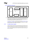
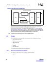
See Section 5.1.7, “Packet Buffer Dimensions” on page 80 for additional information regarding I/O
buffer types. The related driver characteristics are described in this section.
Caution: IXF1104 MAC input signals are not 5 V tolerant. Devices driving the IXF1104 MAC must provide
3.3 V signal levels or use level-shifting buffers to provide 3.3 V-compatible levels. Otherwise,
damage to the IXF1104 MAC will occur.
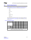
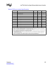
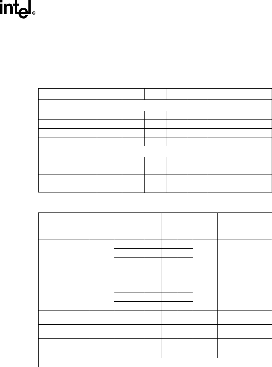
Table 41. DC Specifications
Parameter Symbol Min Typ Max Units Comments
2.5 V CMOS I/O Cells
Input High voltage VIH 1.7 – – V 2.5 V I/Os
Input low voltage VIL – – 0.7 V 2.5 V I/Os
Output High voltage VOH 2.0 – – V 2.5 V I/Os
Output low voltage VOL – – 0.4 V 2.5 V I/Os
3.3 V I/O Cells
Input High voltage VIH 1.7 – – V 3.3 V LVTTL I/Os
Input low voltage VIL – – 0.7 V 3.3 V LVTTL I/Os
Output High voltage VOH 2.4 – – V 3.3 V LVTTL I/Os
Output low voltage VOL – – 0.4 V 3.3 V LVTTL I/Os
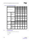
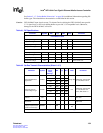
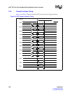
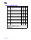
Table 42. SerDes Transmit Characteristics (Sheet 1 of 2)
Parameter Symbol
Normalized
Power
Drive
Settings
1
Min Typ Max Units Comments
Transmit differential
signal level
TxDfPP
0.50 180 230 325
mVpp diff
AVDD1P8_2 terminated
to 1.8V; Rload = 50
Ω
1.00 350 440 700
1.33 425 580 900
2.00 600 770 1050
Transmit common
mode voltage range
TxCMV
0.50 1300 1600 1940
mV
AVDD1P8_2 terminated
to 1.8V; RLoad = 50
ohms; FIR coeffs = 0
1.00 1000 1400 1870
1.33 800 1300 1825
2.00 700 1100 1760
Differential signal rise/
fall time
Diff rise/
fall
1.00 60 96 132 ps
Rload = 50
Ω; 20% to
80% max
Differential output
impedance
TxDiffZ – 60 105 150
Ω diff
Nominal value = 100
Ω
differential
Receiver differential
voltage requirement at
center of receive eye
RxDiffV – 200 – –
mVp-p
diff
–
1. Refer to Section 5.6.2.2, “Transmitter Programmable Driver-Power Levels” on page 104.