Intel
®
IXF1104 4-Port Gigabit Ethernet Media Access Controller
51 Datasheet
Document Number: 278757
Revision Number: 009
Revision Date: 27-Oct-2005
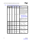
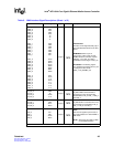
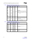
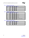
RD3_0
RD2_0
RD1_0
RD0_0
RD3_1
RD2_1
RD1_1
RD0_1
RD3_2
RD2_2
RD1_2
RD0_2
RD3_3
RD2_3
RD1_3
RD0_3
Y7
W7
V7
V8
W9
W11
Y11
Y9
Y23
Y22
Y21
Y20
W18
Y19
Y18
Y17
Input
2.5 V
CMOS
Receive Data.
Bits [3:0] are clocked on the rising edge of RXC.
Bits [7:4] are clocked on the falling edge of RXC.
NOTE: Shares balls with RXD[3:0]_0 on the GMII
interface.
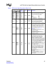
RX_CTL_0
RX_CTL_1
RX_CTL_2
RX_CTL_3
V5
AB11
Y24
V18
Input
2.5 V
CMOS
Receive Control.
RX_CTL is RX_DV on the rising edge of RXC and
a logical derivative of RX_DV and RERR on the
falling edge of RXC.
NOTE: RX_CTL shares the same balls as RX_DV
on the GMII interface.
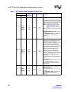
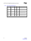
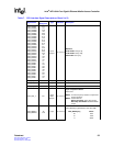
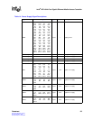
Table 7. CPU Interface Signal Descriptions (Sheet 1 of 2)
Signal Name
Ball
Designator
Type Standard Description
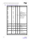
UPX_ADD10
UPX_ADD9
UPX_ADD8
UPX_ADD7
UPX_ADD6
UPX_ADD5
UPX_ADD4
UPX_ADD3
UPX_ADD2
UPX_ADD1
UPX_ADD0
T3
U3
V3
V2
V1
U1
T1
R1
P1
N1
P3
Input 3.3 V LVTTL
UPX_ADD is the address bus from the
microprocessor.
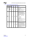
UPX_BADD1
UPX_BADD0
W3
T2
Input 3.3 V LVTTL
16-bit mode: The data word select uses
UPX_BADD1.
8-bit mode: UPX_BADD[1:0] selects the individual
bytes.
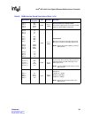
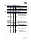
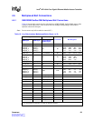
Table 6. RGMII Interface Signal Descriptions (Sheet 2 of 2)
Signal Name
Ball
Designator
Type Standard Description


