


Intel
®
IXF1104 4-Port Gigabit Ethernet Media Access Controller
53 Datasheet
Document Number: 278757
Revision Number: 009
Revision Date: 27-Oct-2005
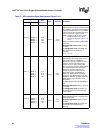
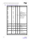
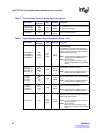
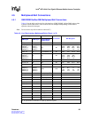
Table 8. Transmit Pause Control Interface Signal Descriptions
Signal Name
Ball
Designator
Type Standard Description
TXPAUSEADD2
TXPAUSEADD1
TXPAUSEADD0
P21
P20
N20
Input
2.5 V
CMOS
TXPAUSEADD[2:0] is the port selection address
for pause frame insertion.
TXPAUSEFR T20 Input
2.5 V
CMOS
TX Pause Interface Strobe.
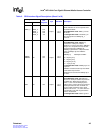
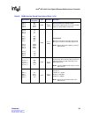
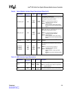
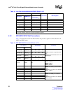
Table 9. Optical Module Interface Signal Descriptions (Sheet 1 of 2)
Signal Name
Ball
Designator
Type Standard Description
TX_DISABLE_0
TX_DISABLE_1
TX_DISABLE_2
TX_DISABLE_3
AB3
AA7
AD16
AA14
Open
Drain
Output*
2.5 V
CMOS
Transmit Disable:
TX_DISABLE_0:3 outputs disable the Optical
Module Interface transmitter. An external pull-up
resistor usually resident in an optical module is
required for proper operation.
NOTE: These signals are multiplexed with the
TXD[4]_n bits of the GMII Interface
NOTE: *Dual-mode I/O
Normal operation: Open drain output
Boundary Scan Mode: Standard CMOS
output
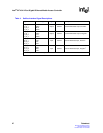
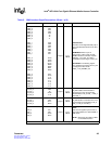
MOD_DEF_0
MOD_DEF_1
MOD_DEF_2
MOD_DEF_3
Y6
AD10
W22
T16
Input
2.5 V
CMOS
MOD_DEF_0:3 inputs determine when an
Optical Module Interface is present.
NOTE: These signals are multiplexed with the
RXD[4]_n bits of the GMII interface.
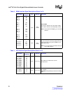
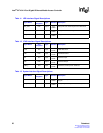
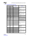
RX_LOS_0
RX_LOS_1
RX_LOS_2
RX_LOS_3
AB5
AA11
V19
T18
Input
2.5 V
CMOS
RX_LOS_0:3 inputs determine when the Optical
Module Interface receiver loses synchronization.
NOTE: These signals are multiplexed with the
RXD[6]_n bits of the GMII interface.
TX_FAULT_0
TX_FAULT_1
TX_FAULT_2
TX_FAULT_3
Y5
AC11
V20
T17
Input
2.5 V
CMOS
TX_FAULT_0:3 inputs determine an Optical
Module Interface transmitter fault.
NOTE: These signals are multiplexed with the
RXD[5]_n bits of the GMII Interface.
RX_LOS_INT P19
Open
Drain
Output*
2.5 V
CMOS
Receiver Loss of Signal Interrupt.
RX_LOS_INT is an open drain interrupt output to
signal an RX_LOS condition.
NOTE: An external pull-up resistor is required
for proper operation.
NOTE: *Dual-mode I/O
Normal operation: Open drain output
Boundary Scan Mode: Standard CMOS
output