Contents
8 Datasheet
Document Number: 278757
Revision Number: 009
Revision Date: 27-Oct-2005
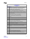
37 RGMII Interface Timing ............................................................................................................141
38 1000BASE-T Transmit Interface Timing...................................................................................142
39 1000BASE-T Receive Interface Timing....................................................................................143
40 SerDes Timing Diagram ...........................................................................................................144
41 MDC High-Speed Operation Timing.........................................................................................145
42 MDC Low-Speed Operation Timing..........................................................................................145
43 MDIO Write Timing Diagram ....................................................................................................146
44 MDIO Read Timing Diagram ....................................................................................................146
45 Bus Timing Diagram.................................................................................................................147
46 Write Cycle Diagram.................................................................................................................147
47 CPU Interface Read Cycle AC Timing......................................................................................149
48 CPU Interface Write Cycle AC Timing......................................................................................149
49 Pause Control Interface Timing................................................................................................151
50 JTAG AC Timing.......................................................................................................................152
51 System Reset AC Timing .........................................................................................................153
52 LED AC Interface Timing..........................................................................................................154
53 Memory Overview Diagram ......................................................................................................155
54 Register Overview Diagram......................................................................................................156
55 CBGA Package Diagram..........................................................................................................225
56 CBGA Package Side View Diagram.........................................................................................226
57 FC-PBGA Package (Top and Bottom Views)...........................................................................227
58 FC-PBGA Mechanical Specifications .......................................................................................228
59 Package Marking Example.......................................................................................................229
60 Ordering Information – Sample ................................................................................................230
Tables
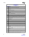
1 Ball List in Alphanumeric Order by Signal Name........................................................................24
2 Ball List in Alphanumeric Order by Ball Location........................................................................30
3 SPI3 Interface Signal Descriptions.............................................................................................39
4 SerDes Interface Signal Descriptions.........................................................................................47
5 GMII Interface Signal Descriptions.............................................................................................48
6 RGMII Interface Signal Descriptions ..........................................................................................50
7 CPU Interface Signal Descriptions .............................................................................................51
8 Transmit Pause Control Interface Signal Descriptions ...............................................................53
9 Optical Module Interface Signal Descriptions.............................................................................53
10 MDIO Interface Signal Descriptions ...........................................................................................54
11 LED Interface Signal Descriptions..............................................................................................55
12 JTAG Interface Signal Descriptions............................................................................................55
13 System Interface Signal Descriptions.........................................................................................55
14 Power Supply Signal Descriptions..............................................................................................56
15 Ball Usage Summary.................................................................................................................. 57
16 Line Side Interface Multiplexed Balls..........................................................................................58
17 SPI3 MPHY/SPHY Interface.......................................................................................................59
18 Definition of Output and Bi-directional Balls During Hardware Reset.........................................61
19 Power Supply Sequencing .........................................................................................................64
20 Pull-Up/Pull-Down and Unused Ball Guidelines.........................................................................64
21 Analog Power Balls ....................................................................................................................65
22 CRC Errored Packets Drop Enable Behavior.............................................................................69
23 Valid Decodes for TXPAUSEADD[2:0].......................................................................................74
24 Operational Mode Configuration Registers ................................................................................76


