


Intel
®
IXF1104 4-Port Gigabit Ethernet Media Access Controller
55 Datasheet
Document Number: 278757
Revision Number: 009
Revision Date: 27-Oct-2005
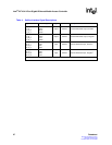
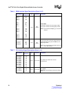
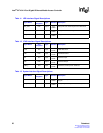
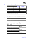
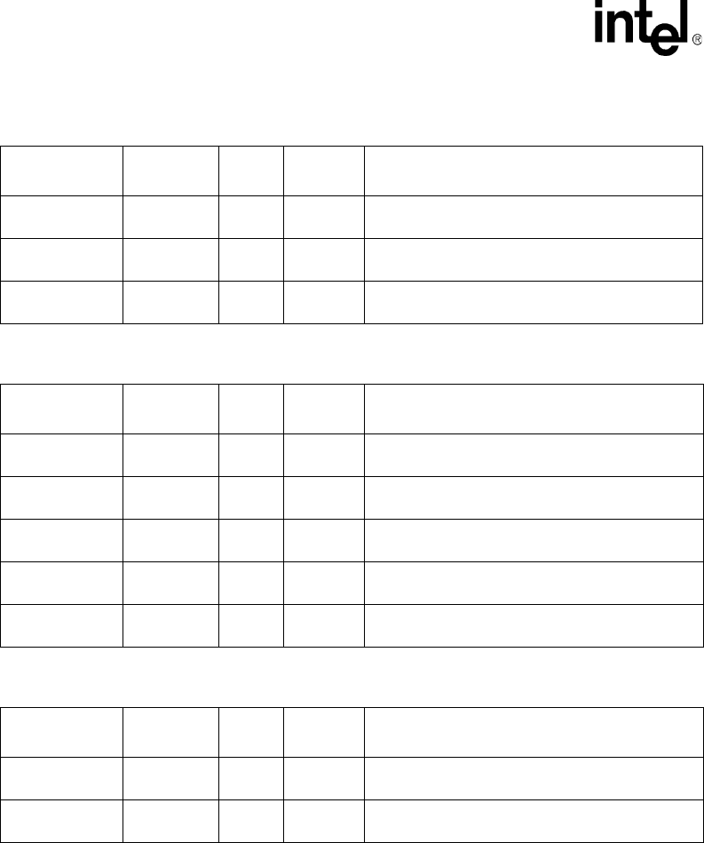
Table 11. LED Interface Signal Descriptions
Signal Name
Ball
Designator
Type Standard Description
LED_CLK K24 Output
2.5 V
CMOS
LED_CLK is the clock output for the LED block.
LED_DATA M22 Output
2.5 V
CMOS
LED_DATA is the data output for the LED block.
LED_LATCH L22 Output
2.5 V
CMOS
LED_LATCH is the latch enable for the LED block.
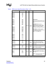
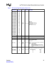
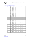
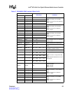
Table 12. JTAG Interface Signal Descriptions
Signal Name
Ball
Designator
Type Standard Description
TCLK J22 Input
3.3 V
LVTTL
JTAG Test Clock
TMS H22 Input
3.3 V
LVTTL
Test Mode Select
TDI J24 Input
3.3 V
LVTTL
Test Data Input
TDO H24 Output
3.3 V
LVTTL
Test Data Output
TRST_L J23 Input
3.3 V
LVTTL
Test Reset; reset input for JTAG test
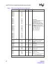
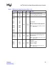
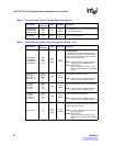
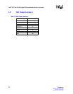
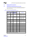
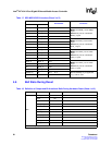
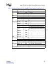
Table 13. System Interface Signal Descriptions
Signal Name
Ball
Designator
Type Standard Description
CLK125 AD19 Input
2.5 V
CMOS
CLK125 is the input clock to PLL; 125 MHz +/-
50 ppm
SYS_RES_L AD12 Input
2.5 V
CMOS
SYS_RES_L is the system hard reset (active Low).