


Configuring Frame Relay
Introduction
MAX 6000/3000 Network Configuration Guide Preliminary January 4, 2001 5-3
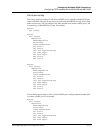
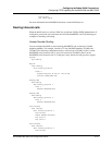
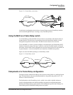
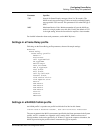
Figure 5-2. Frame Relay concentrator
In this kind of configuration, the decision to forward frames onto the Frame Relay interface
can be made through OSI layer 3 (routing), or by Frame Relay Direct.
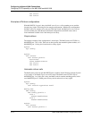
Using the MAX as a Frame Relay switch
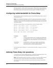
As a Frame Relay switch, the MAX receives frames on one interface and transmits them on
another interface. The decision to forward frames onto the Frame Relay interface is made
through the assignment of circuit names. The MAX router software is not involved.
To use the MAX as a switch, you must configure a circuit that pairs two Frame Relay DLCI
interfaces. Instead of going to the layer 3 router for a decision on which interface to forward
the frames, it relies on the circuit configuration to relay the frames received on one interface to
its paired interface. A circuit is defined in two Connection or RADIUS user profiles.
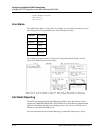
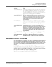
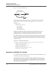
Figure 5-3 shows the MAX operating as a Frame Relay switch:
Figure 5-3. Frame Relay switch
Components of a Frame Relay configuration
The physical link to another Frame Relay device must be nailed (similar to a dedicated leased
line). The administrator allocates nailed bandwidth in a line profile (the profile of a T1, E1,
SWAN, or other network line).
The link interface to the Frame Relay device, which is also called a datalink, references
specific nailed bandwidth in the MAX and defines the operations and link management
functions the MAX performs on the interface. The administrator specifies these settings in a
Frame Relay profile or RADIUS frdlink pseudo-user profile.
Frame Relay
DLCI 50
PPP
FR switch-3
FR switch-2
FR switch-1
DLCI 100 DLCI 200