


Configuring Frame Relay
Configuring a DLCI logical interface
MAX 6000/3000 Network Configuration Guide Preliminary January 4, 2001 5-13
(every 60 seconds). It also sends a Full Status report in response to requests from the other
switch. If it does not receive a Status Enquiry within a 15-second interval (T392), it records an
error.
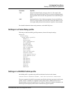
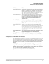
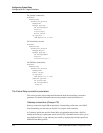
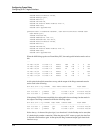
Following is a comparable RADIUS profile:
frdlink-max-3 Password="ascend", User-Service=Dialout-Framed-User
Ascend-FR-Profile-Name="switch-3",
Ascend-Call-Type=Nailed,
Ascend-FR-Type=Ascend-FR-NNI,
Ascend-FR-Nailed-Grp=52,
Ascend-FR-Link-Mgt=Ascend-FR-T1-617D,
Ascend-Data-Svc=Nailed-64K,
Ascend-FR-N391=6,
Ascend-FR-T391=10,
Ascend-FR-T392=15
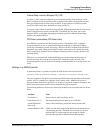
Configuring a DLCI logical interface
A Connection profile defines a DLCI interface. The same settings can be specified in a
RADIUS permconn pseudo-user profile.
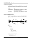
Overview of DLCI interface settings
Administrators configure a Connection or RADIUS permconn profile that specifies a
connection to a far end device across Frame Relay. The first hop of the connection is known by
the DLCI assigned in the profile.
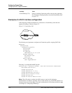
A DLCI is an integer between 16 and 991 that uniquely identifies a specific endpoint in the
Frame Relay network. The Frame Relay administrator must provide a valid DLCI for each
logical interface to a Frame Relay network.
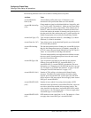
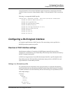
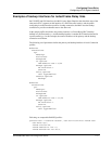
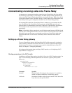
Settings in a Connection profile
All connections that use Frame Relay must specify the name of a configured Frame Relay
profile that defines the data link between the MAX and the Frame Relay network. Forwarded
or routed connections over the Frame Relay link use the following sets of parameters (shown
with sample settings):
Ethernet
Answer
Encaps...
PPP=Yes
FR=Yes
PPP Options...
Route IP=Yes