


5-12 Preliminary January 4, 2001 MAX 6000/3000 Network Configuration Guide
Configuring Frame Relay
Defining Frame Relay link operations
Examples of an NNI link interface
An NNI interface implements procedures used by Frame Relay switches to communicate
status between them. The MAX uses these procedures to inform its peer switch about the status
of PVC segments from its side of the Frame Relay network, as well as the integrity of the
datalink between them. The procedure is bidirectional. The switches act as both the user side
(DTE) and network side (DCE) in that they both send Status Enquiries and respond to them.
Because NNI is bidirectional, all of the link management values defined in the Frame-Relay
profile are used. The values of the N391, N392, N393, and T391 parameters define the user
side of the NNI. These values define the timing of the status enquiries the MAX MAX sends to
its peer switch and the boundary conditions that define link integrity. The values of the T392l,
DCE N392, and DCE N393 parameters are used by the network side of the NNI to define the
parameters of the Status Enquiries it expects from the its peer switch.
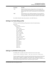
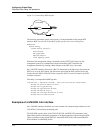
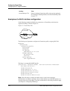
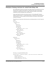
Figure 5-6 shows a MAX with an NNI interface:
Figure 5-6. Frame Relay NNI interface
To operate as a switch, the MAX requires a hard-coded circuit configuration in two
Connection profiles. It relies on the circuit configuration to relay the frames received on one of
the circuit endpoints to the other circuit endpoint. For details about circuit configuration, see
“Configuring the MAX as a Frame Relay switch” on page 5-25.
Note: The two Frame Relay endpoints that make up the circuit do not require NNI interfaces.
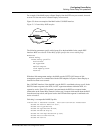
The following parameters specify the nailed group 52 as the bandwidth for the NNI interface to
Switch-3 (Figure 5-6). Make sure that the Frame-Relay profile specifies the correct nailed
group.
Ethernet
Frame Relay
Frame Relay profile
Active=Yes
FR Type=NNI
Nailed Grp=52
Link Mgmt=T1.617D
N391=6
T391=10
T392=15
With these link management settings, the MAX uses the ANSI Annex D link management
protocol to communicate with Switch-3. It sends a Status Enquiry for Link Integrity
Verification to Switch-3 every 10 seconds, and requests a Full status report every sixth enquiry
FR switch-3
FR switch-2
NNI NNI