


5-28 Preliminary January 4, 2001 MAX 6000/3000 Network Configuration Guide
Configuring Frame Relay
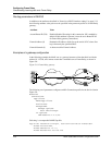
Configuring the MAX as a Frame Relay switch
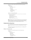
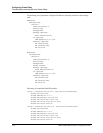
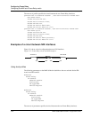
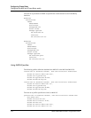
The next set of profiles specifies the circuit between the two Frame Relay interfaces:
permconn-max-10 Password="ascend" , User-Service=Dialout-Framed-User
User-Name="max6",
Framed-Protocol=FR-CIR,
Ascend-Route-IP=Route-IP-No,
Ascend-FR-DLCI=100,
Ascend-FR-Profile-Name="max",
Ascend-FR-Circuit-Name="fr-cir1"
permconn-max-11 Password="ascend", User-Service=Dialout-Framed-User
User-Name="p130",
Framed-Protocol=FR-CIR,
Ascend-Route-IP=Route-IP-No,
Ascend-FR-DLCI=200,
Ascend-FR-Profile-Name="p130east",
Ascend-FR-Circuit-Name="fr-cir1"
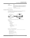
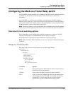
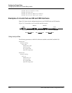
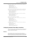
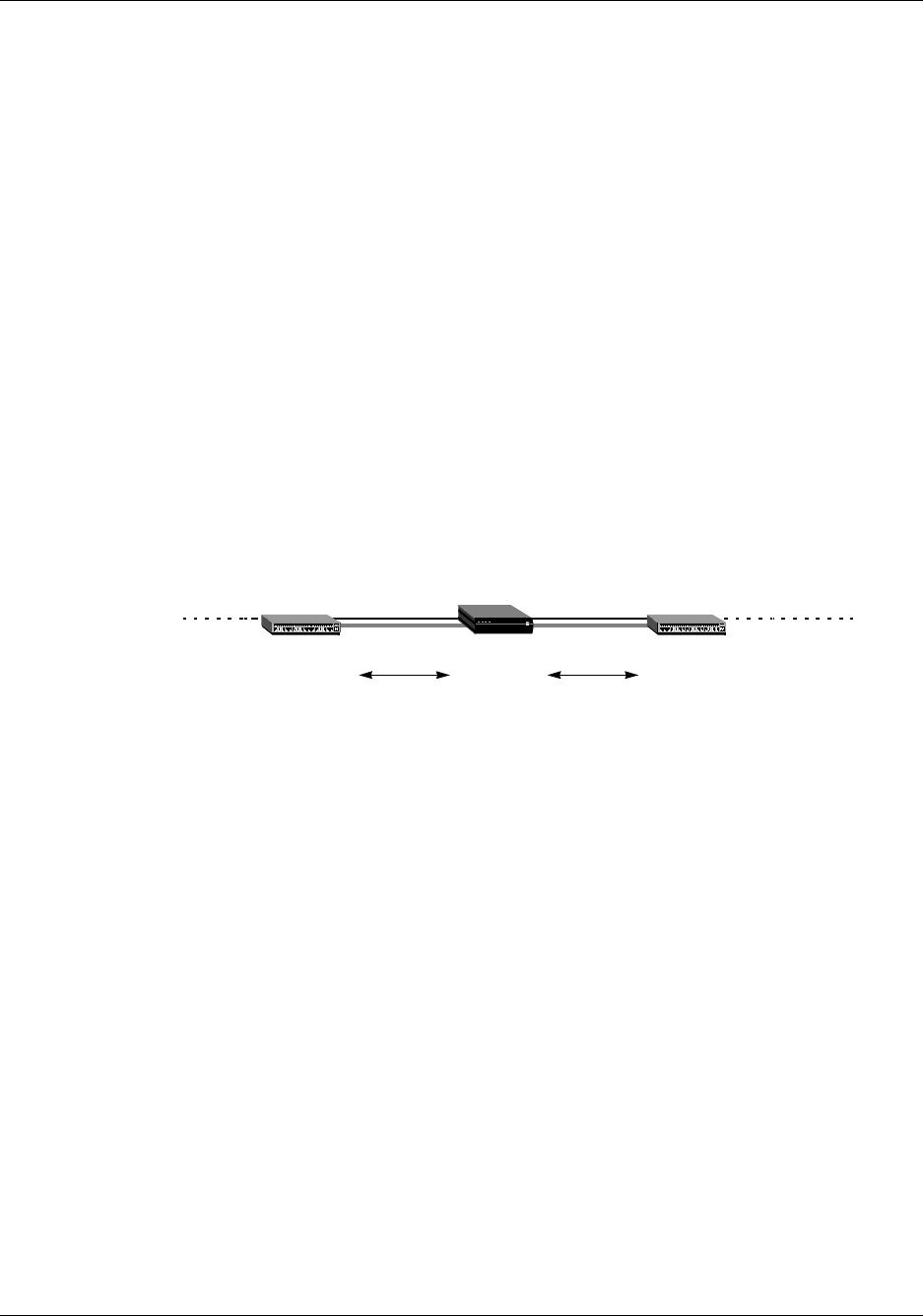
Examples of a circuit between NNI interfaces
Figure 5-11 shows a circuit configuration that uses NNI interfaces.
Figure 5-11. Frame Relay circuit with NNI interfaces
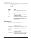
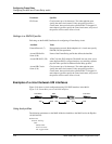
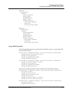
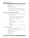
Using local profiles
The following parameters on the MAX define the datalinks to the two switches labeled FR-
Asnd-A and FR-Asnd-B:
Ethernet
Frame Relay
fr-asnd-a
Name=fr-asnd-a
Active=Yes
FR Type=NNI
Nailed Grp=333
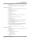
Ethernet
Frame Relay
fr-asnd-b
Name=fr-asnd-b
Active=Yes
FR Type=NNI
Nailed Grp=444
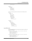
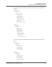
The next set of parameters specifies the circuit between the two Frame Relay interfaces:
FR-Asnd-BFR-Asnd-A
DLCI 100
NNI
NNI
DLCI 200
NNI
NNI